Flap Handle Improvements
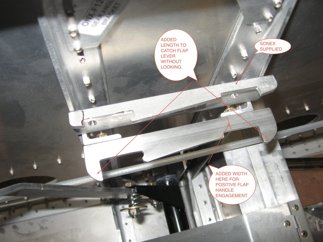
The Sonex supplied flap engagement was not to my liking.To engage the flaps you would have to look at it as when you pulled the flap handle back it is easy to miss the detent and go too far so you would have to look ,to engage at the right spot.By adding the extra length when you pull the handle back it will hit the stop and you know you simply have to let go and it will engage.
Same when you dump the flaps .As you push the flap lever forward it will hit the forward stop and again you can simply let it go and the spring will engage it.
I also added the width as noted above so that the flap handle automatically springs into place.With the original it barely engaged.
Same when you dump the flaps .As you push the flap lever forward it will hit the forward stop and again you can simply let it go and the spring will engage it.
I also added the width as noted above so that the flap handle automatically springs into place.With the original it barely engaged.
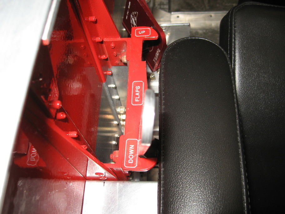
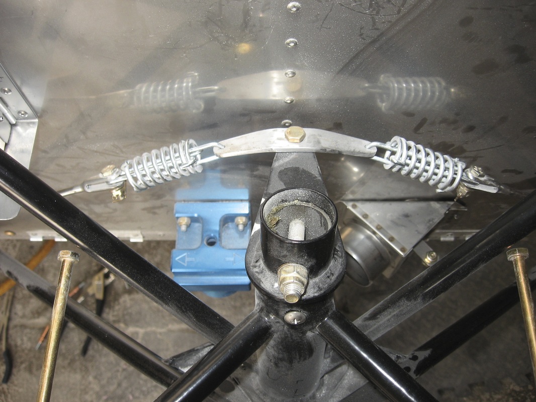
Couple of pics showing the positive engagement.
Rudder Cables
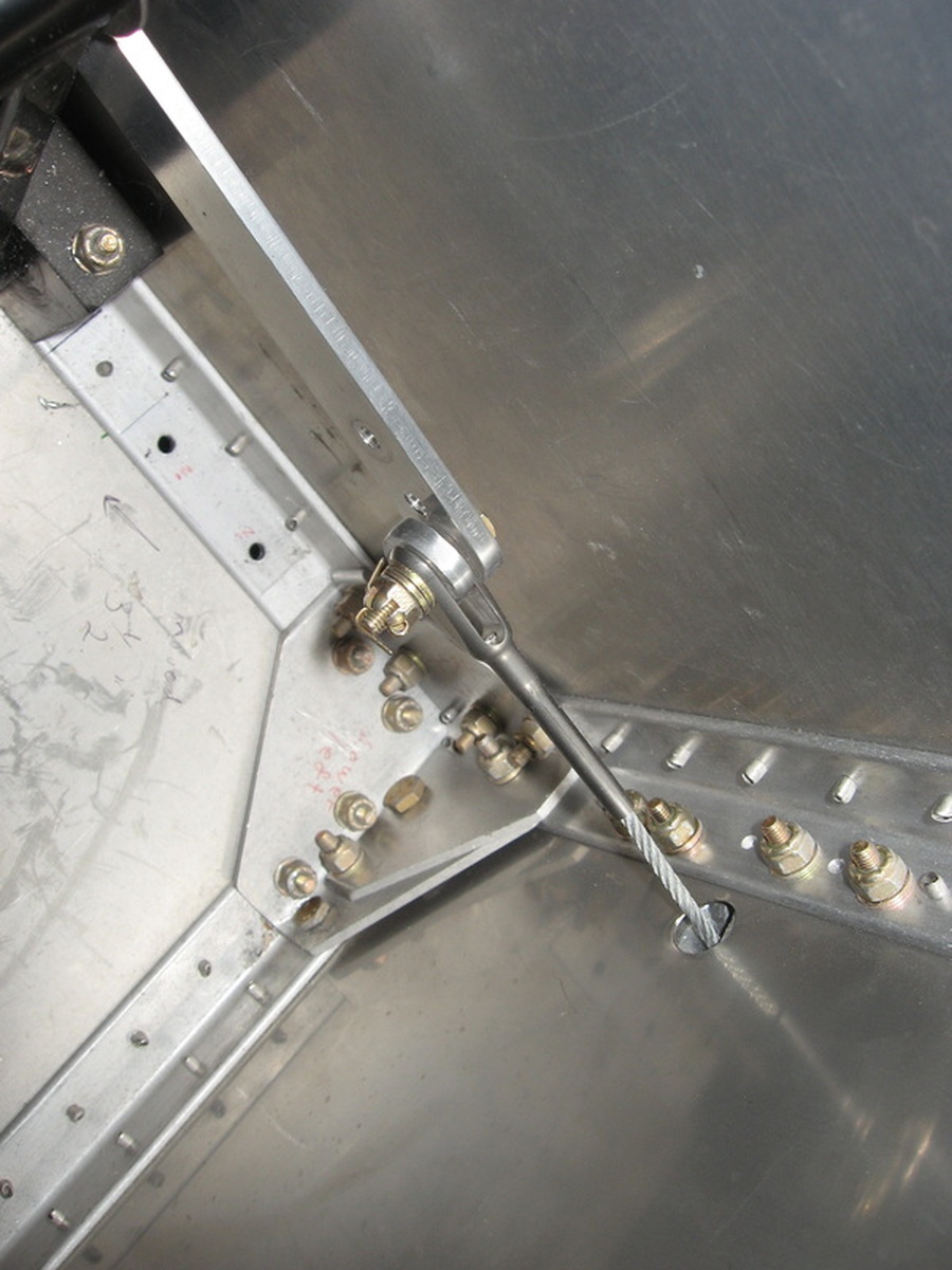
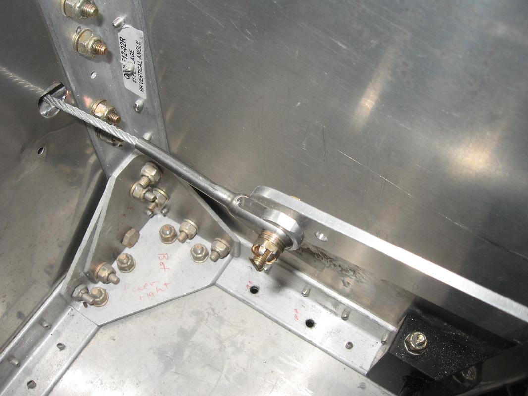
Getting the cables to run smoothly is a bit of a challenge if you chose the Tri-gear .From the rudder horn to the rudder pedals is pretty easy if you follow the revisions.I had to enlarge the cut outs in the rear fuse for the cable pass through both sides.
From the rudder pedals to the nose wheel is the challenging part.Getting the cables to pass through the firewall holes without rubbing anywhere took a lot of trial and error.Finally after getting the right tension on the cables from the cable adjuster to the nose wheel and off setting the cable s at the adjuster I was finally able to achieve a smooth movement.
From the rudder pedals to the nose wheel is the challenging part.Getting the cables to pass through the firewall holes without rubbing anywhere took a lot of trial and error.Finally after getting the right tension on the cables from the cable adjuster to the nose wheel and off setting the cable s at the adjuster I was finally able to achieve a smooth movement.
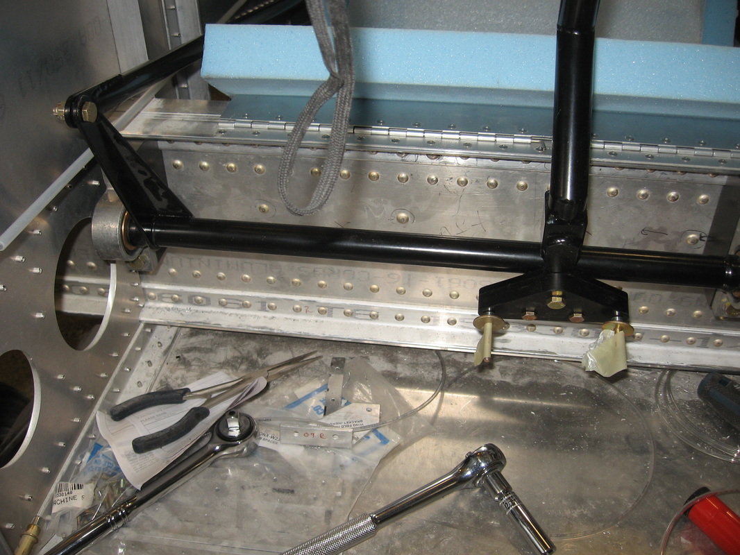
Elevator Push Rod
Maybe I missed the elevator pushrod 101 class or missed a step in the plans but getting the push rod in place is a major PITA.
I had to lengthen the oblong holes that it goes through to get it in place.Grind fit,grind fit,grind fit.
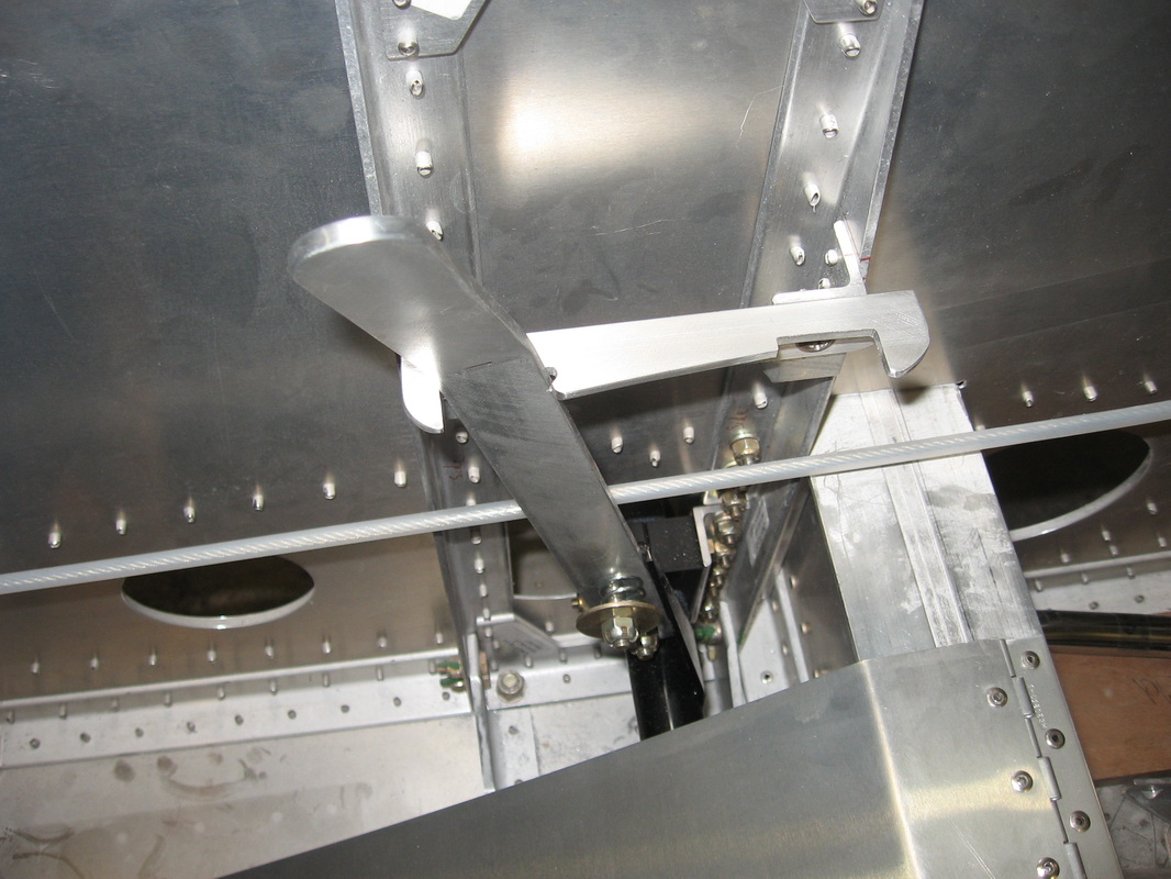
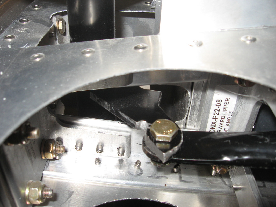
Once I got it in place then I connected it to the elevator horn and the idler and then discovered that I had more grinding to do as it was rubbing in a few places.Here are some pics of my days work.
I had to lengthen the oblong holes that it goes through to get it in place.Grind fit,grind fit,grind fit.
Once I got it in place then I connected it to the elevator horn and the idler and then discovered that I had more grinding to do as it was rubbing in a few places.Here are some pics of my days work.
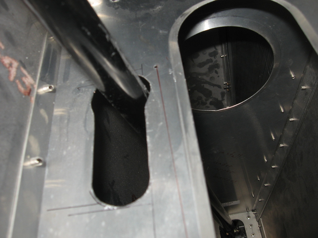
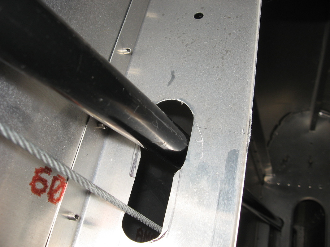
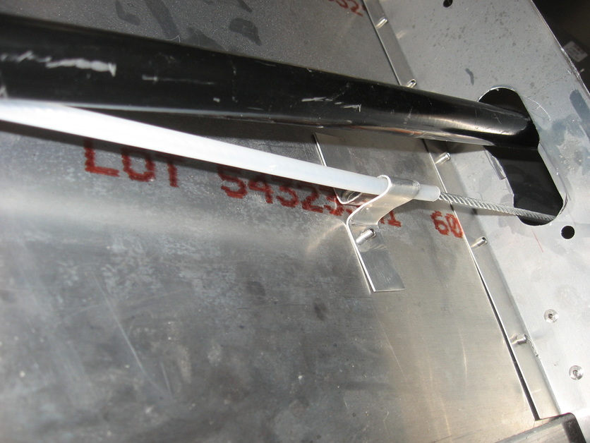
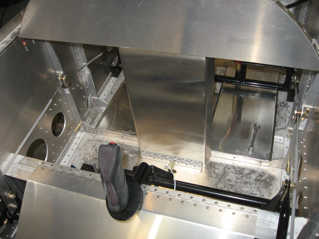
This pic shows how I keep the rudder cable from rubbing on the elevator push rod
|
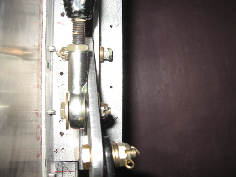
The elevator idler
|
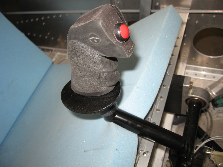
The Fat Boy grip
Foot wells
I made two foot well pans to facilitate foot movement when using the rudder pedals.
The centre console I am still working on.It will house the Andair fuel shut and quite possibly a fuse box,plus what ever else makes sense.Cabin heat control is another possibility.Lots of space to use,but I mainly designed it for the fuel shut off .
The centre console I am still working on.It will house the Andair fuel shut and quite possibly a fuse box,plus what ever else makes sense.Cabin heat control is another possibility.Lots of space to use,but I mainly designed it for the fuel shut off .
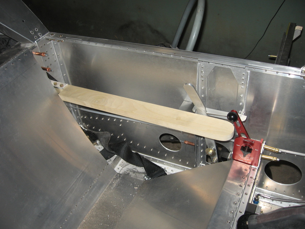
Throttle placement
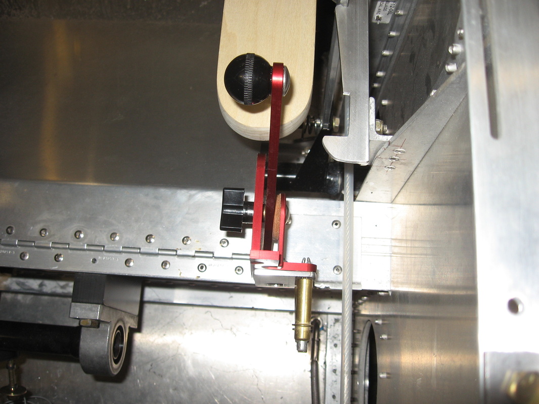
I have seen some different ideas where to place the throttle.The one thing I was sure of was I was not going to place it ala sonex's idea of where to put it.Too high up.Since I also eliminated the Sonex Brake Handle I sat in the cockpit and thought it felt comfortable with the throttle sitting on the main Spar so thats where I placed it .I made a bracket to attach it to and it is in a comfortable position for my left arm.I replaced the black handle with a shorter type ball ( 14-24 thread) so my leg would not have any chance of hitting it.
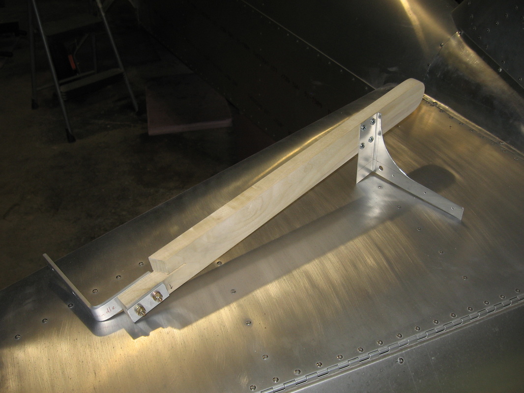
Once I did that it seemed like a natural to add an arm rest with the throttle at the end of it.So here it is minus the padded leather covering on the arm rest.
The wood is light weight soft wood.
The arm rest is extremely comfortable and strong.
Now I have to make a box for maps,etc between the arm rest and the side of the fuse.