
Fuselage Build F22 to F14
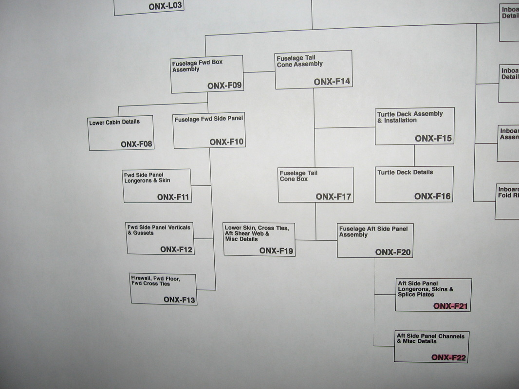
I will be doing this by the plans ,working off boxes one at a time from the fuse tree,starting with
F-22
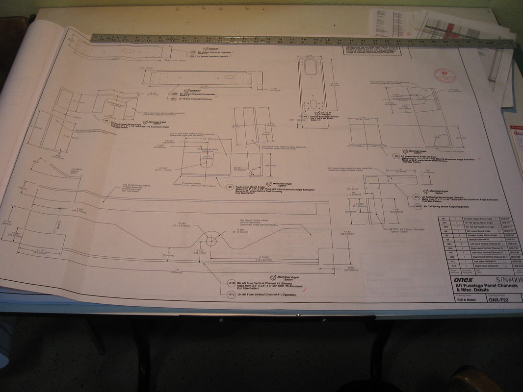
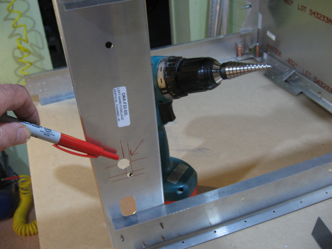
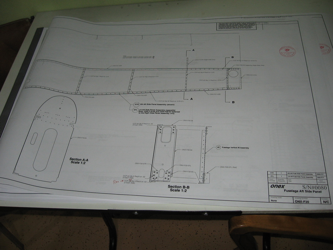
I would drill out ONX-F22-07L &07R to 1/4" (check ahead in plans to see this.A bolt will be passing through these 2 tail spring mounts)now before assembling it as you can put it in your drill press easily now.I wound up doing it after it was assembled .Doable but not as easy if you get-r-done now.
Also see revisions for F22 page .(see below) Best to measure and add these before assembly.
The one on the right I did before assembly .One on left I missed and had to do it after.
|
|
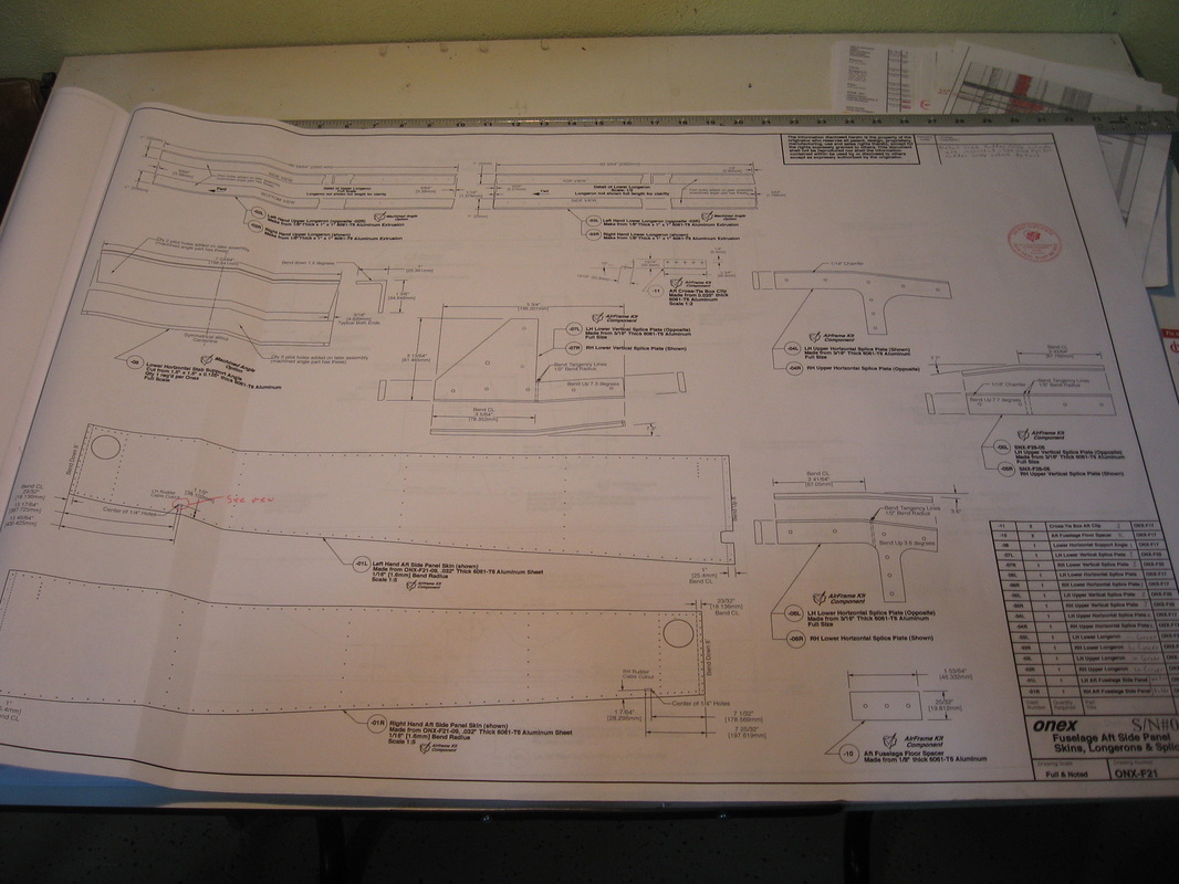
F-21
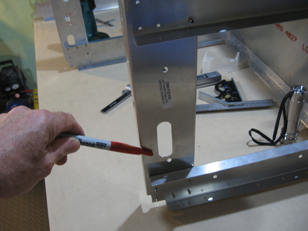
07 L &R,06L&R,05L&R all require bends which I will do on the arbor press.Pay attention to the radius ie;for 1/2" radius use a 1" bar etc.
It's easiest if you put the chamfer's in before the bends.I did mine on my router table with a 45* cutter.
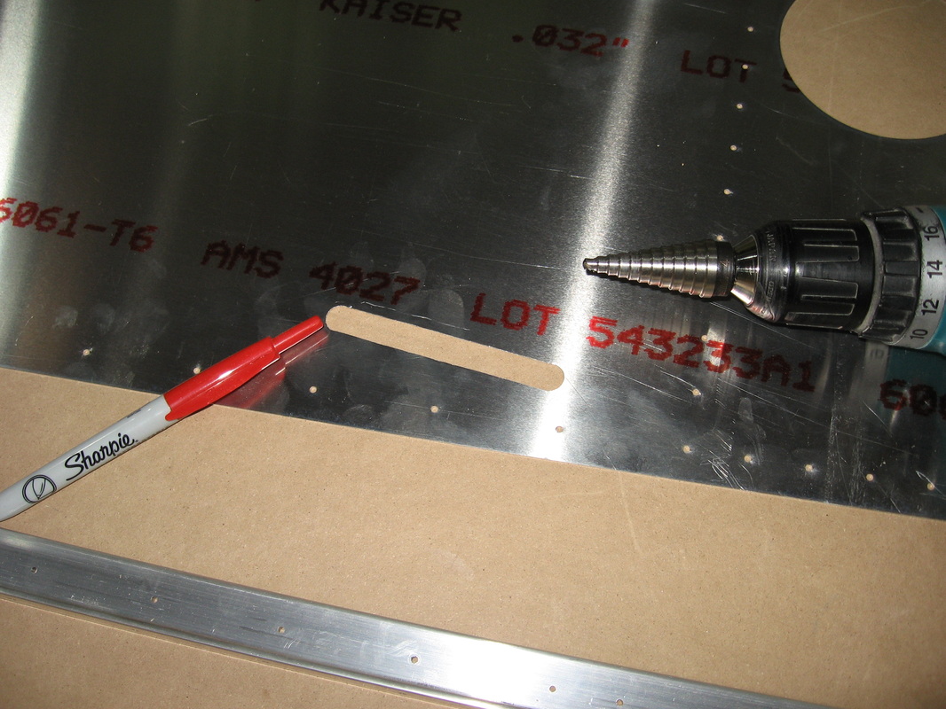
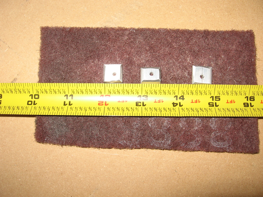
The rudder cable cutouts have a revision which points you to the first page of the fuse pages.I recommend you purchase a step drill (shown below)as it makes cutting the 1/2" holes very neat.I cut between the holes using a dremel tool but i think i will try a jig saw for the other side with a metal cutting blade.I'm certain it will be faster and neater.Well faster yes but maybe not as neat.
The bends on both ends of the fuse sides require a metal brake.I bought a 30" at Princess Auto for $69 and it worked great .
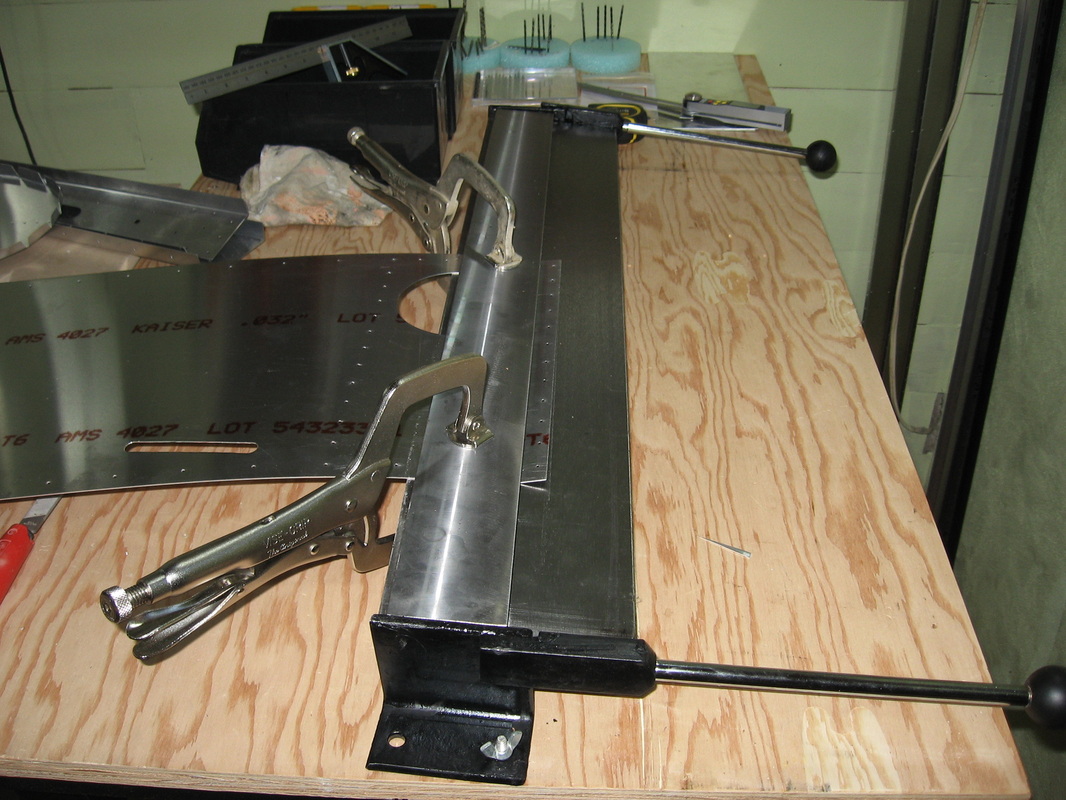
If your sharp you will see that I bent this end in the wrong direction.The next photo from Joe a.k.a. Southernmage over at Onexplans.com will make it clear.
F-20
I up drilled the upper and lower longerons and riveted the aft sides where noted on the plans.No rivets where the turtle deck will go and 2 places each side lower left front
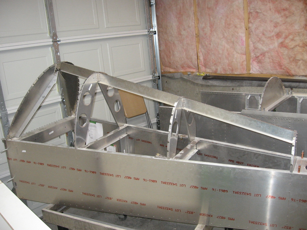
I then clecoed the 2 sides together to see how everything would play out and discovered 2 holes on the bottom of the rear bulkhead channel that did not line up with the 2 holes in the longerons?
Every other hole lines up perfectly.I even laid the bottom panel on and all the matched holes lined up with all the holes in the lower longerons .
Have e-mailed Kerry with a picture ,so I will wait and see what he says.
The 2 offending holes that don't line up.Top and sides are clecoed .These will get drilled out to 3/16" so I'm hoping I will wind up with just 1 hole as the 2 holes are 1/16" off.
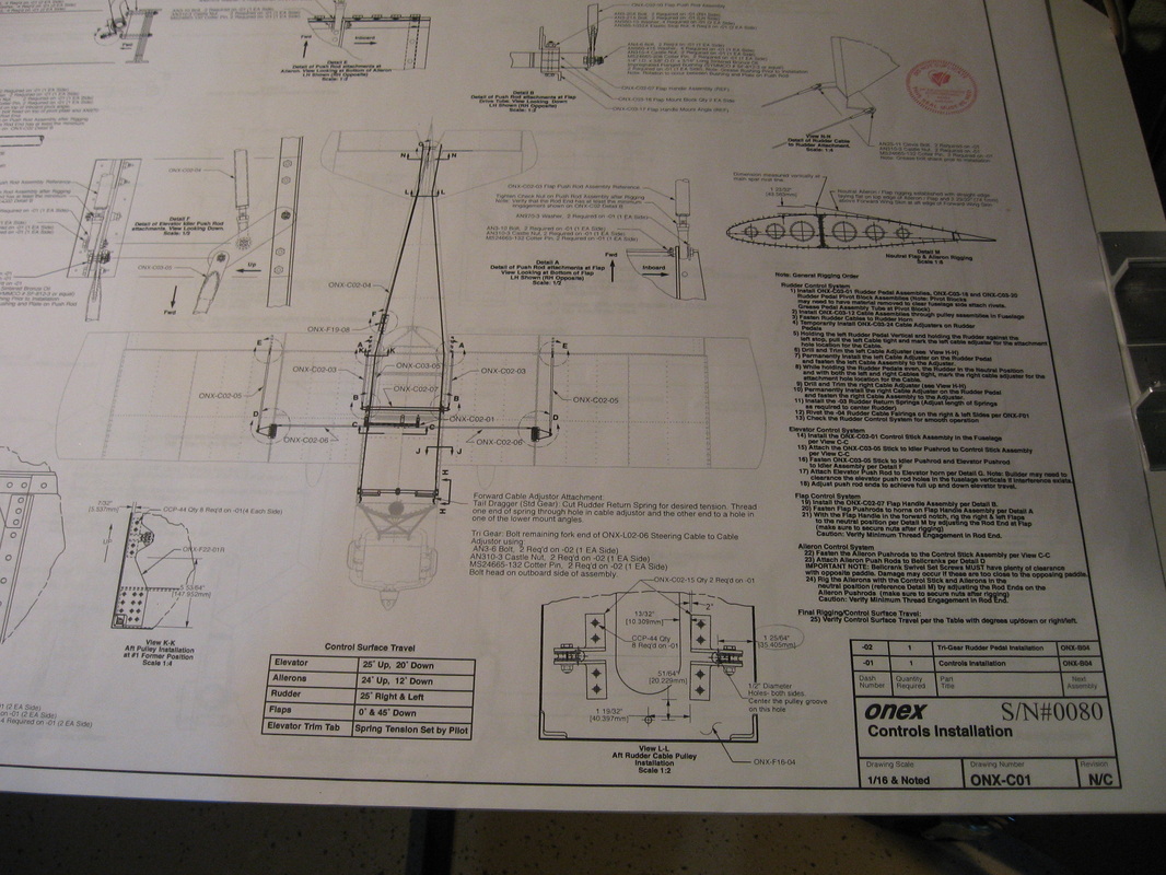
Moving ahead in the plans to page C01 and C02 there are 2 assembly's to make for the last bulkhead (see view L-L above).Easier to do the work on the bulkhead now before it gets riveted in.The assembly's get made from the 2"x 2" angle you received.
The 2 rudder cable holes above.
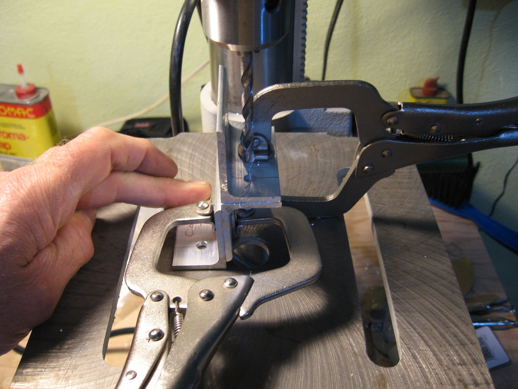
and the 4 bracket angles above.I clamped the 2 pc's together and drilled them as one to accept the bolt using a 3rd pc on the bottom to keep it square to the drill bit.
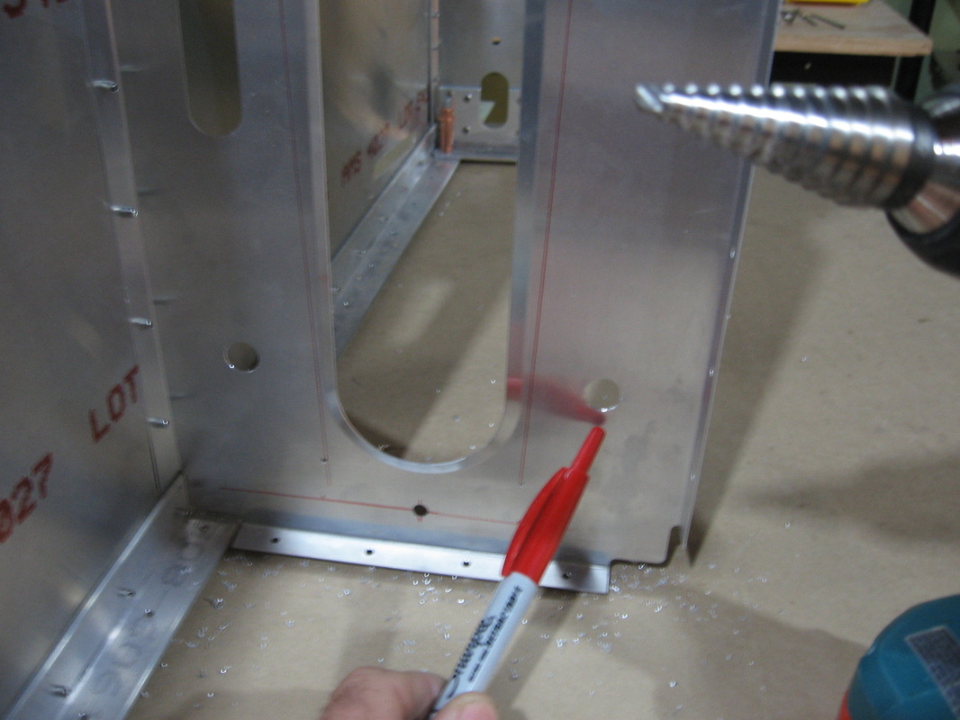
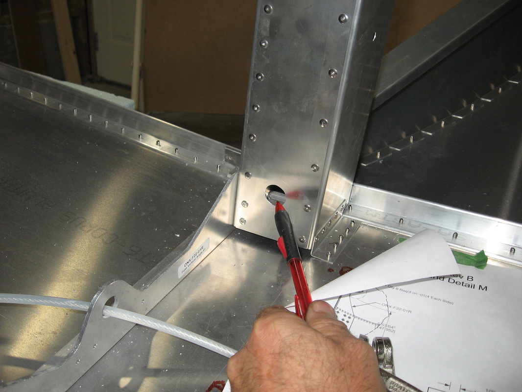
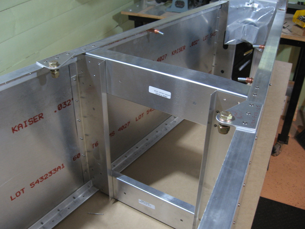
You will need an access hole cut into the left side skin to be able to tighten the bolt and nut that will hold the Tail skid in my case and also if I ever decide to change to a tail wheel I will need this hole to get at the bolt again.
As can be seen it intersects the longeron right where you see it touching in the photo.The fact that I can use the 1/4" drill bit from the inside like this will allow me to accuratly center the hole in the side skin.
Drilling slowly with just enough pressure to start the hole will leave an impression so I can switch to a 1/8" 6"long bit to finish the hole through completely.
Then from the outside I drilled up to a 1/4" hole to allow me to use the step drill bit I used on the side skins above................orIt was pointed out to me that it would also be acceptable to attach the 2 L brackets after the fuse sides are riveted together with the tail skid attached.you would simply rivet it from underneath
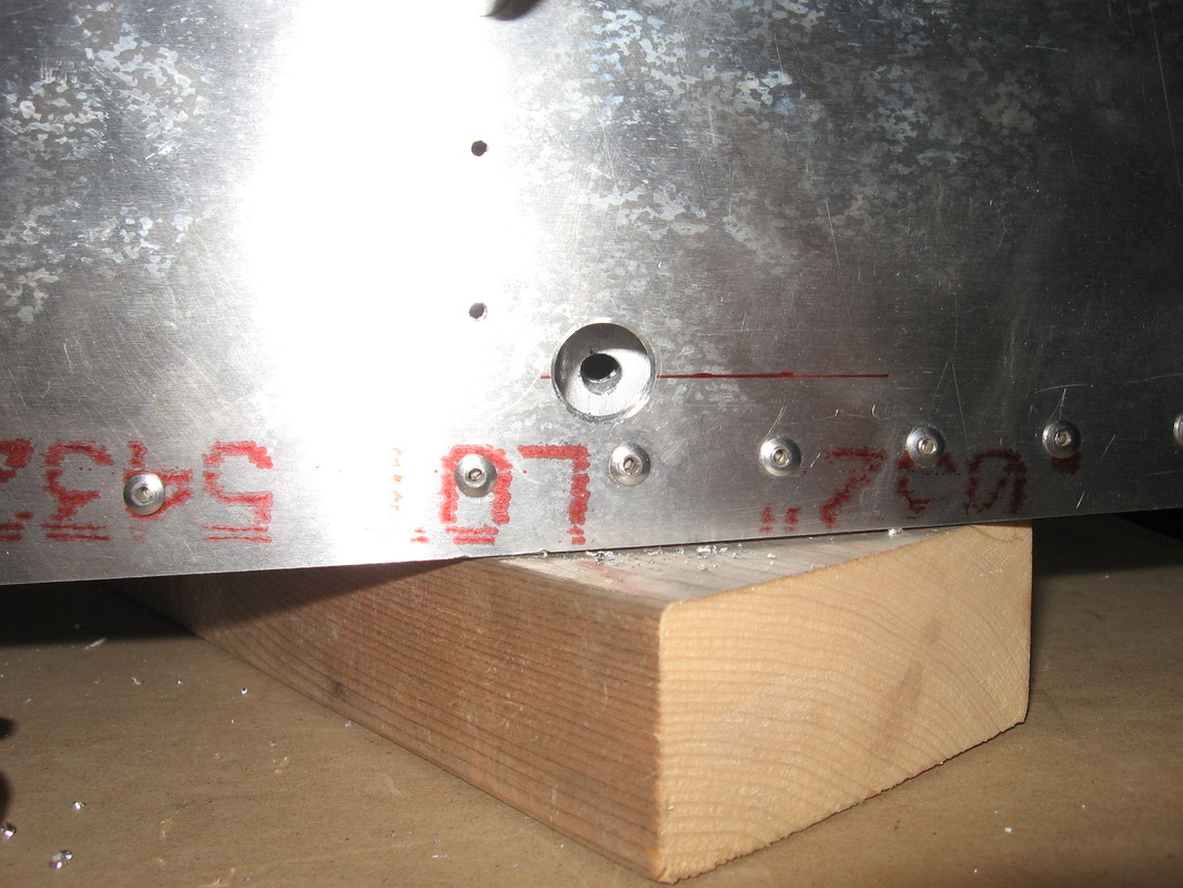
Step drilled up to 5/8"and lined up with the tail spring mount angle holes.
F19
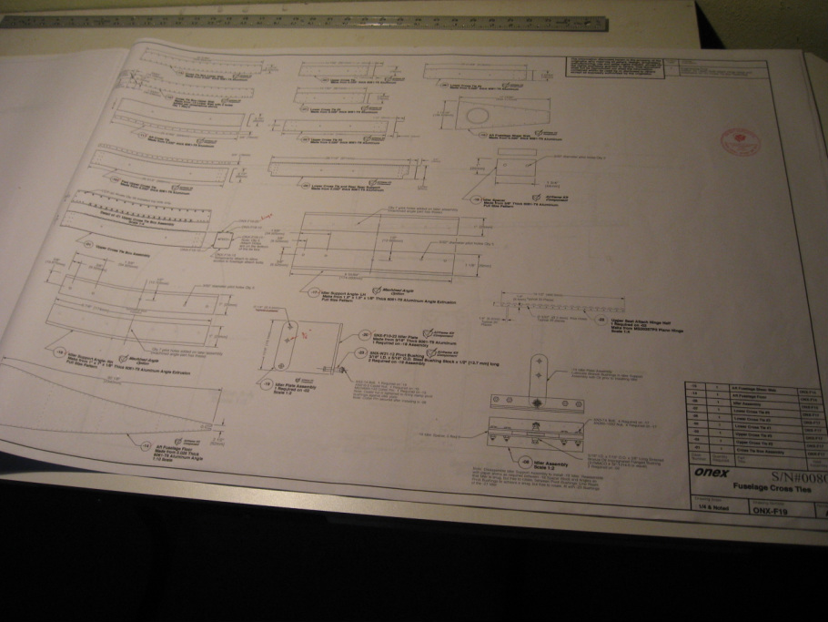
Two assemblies on this page ;1) the upper cross-tie which requires four holes to be drilled on one of the ONX-F19-13's you received to make the ONX-F19-12
shown on drawing.
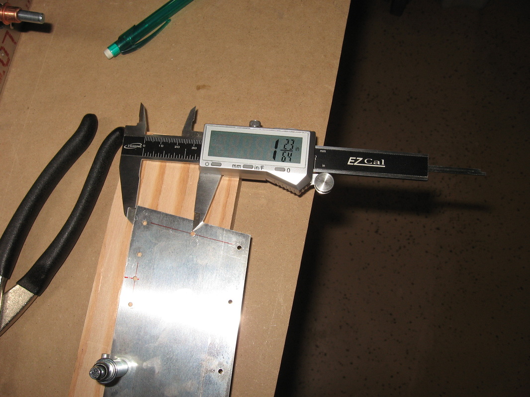
This is what I use for almost all measurements.
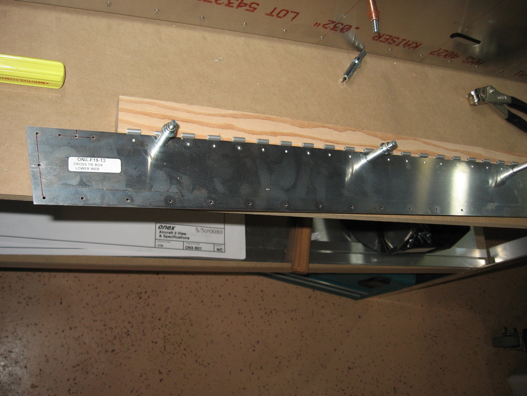
Transferring the holes to the hinge is as easy as setting the hinge against the the edge of the cross tie box and drilling 1/32" holes.
Upper cross tie box assembly up drilled and deburred.Ready for rivets.Only the top gets riveted the bottom is left cleco'ed. Careful with the back side of this assembly ie; pay attention to the "up"written on the plans.
That's the in and out deburr tool in the drill chuck.Some people in the forums have complained that they don't work.
I paid $93 with tax for this tool and consider it great value for the time it saves.
As to the people that claim it doesn't work I have no answer.One thing to remember is that it won't look like a hand debured edge.All you want is to remove enough so that you don't feel any burrs .It just leaves a barely discernible shiny edge around the hole.Just because you can't see the chamfer like you can with a hand deburr tool doesn't mean that it is not working.I'm able to deburr all the holes on the top that you see here in about one and a half minutes both sides of three parts.
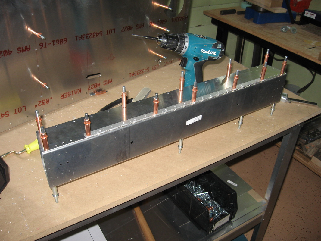
I slipped the above picture in in case anyone wants to add these holes at the bottom of the cross tie box.I just didn't like the idea of never being able to see the nuts on the bolts that are hidden inside the box after you rivet the bottom on.With a flash light and mirror i will be able to inspect them once a year when I do the annual.
2ND assembly on F-19
The Idler Assembly
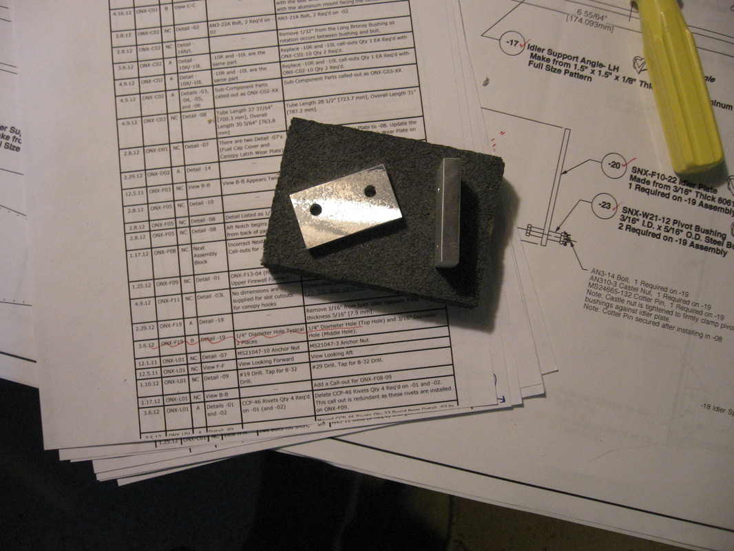
A revision calls for F19-18 spacers to be reduced to 5/16" thick
I did this on my table saw but don't try it unless you have a zero clearance insert for your table saw.see below and use a thin push stick to advance the pieces through the saw blade.
A revision calls for F19-18 spacers to be reduced to 5/16" thick
I did this on my table saw but don't try it unless you have a zero clearance insert for your table saw.see below and use a thin push stick to advance the pieces through the saw blade.
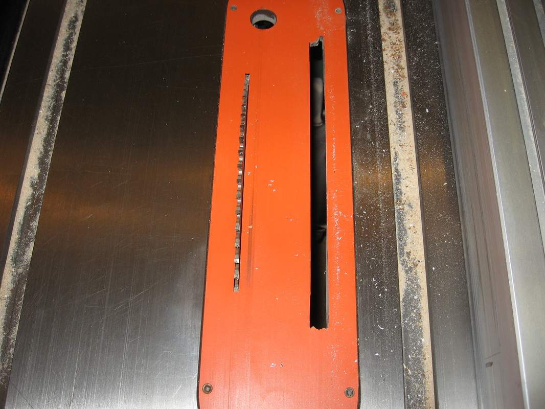
I took 2 passes for each one taking half the amount off the first pass.the finished pc's below
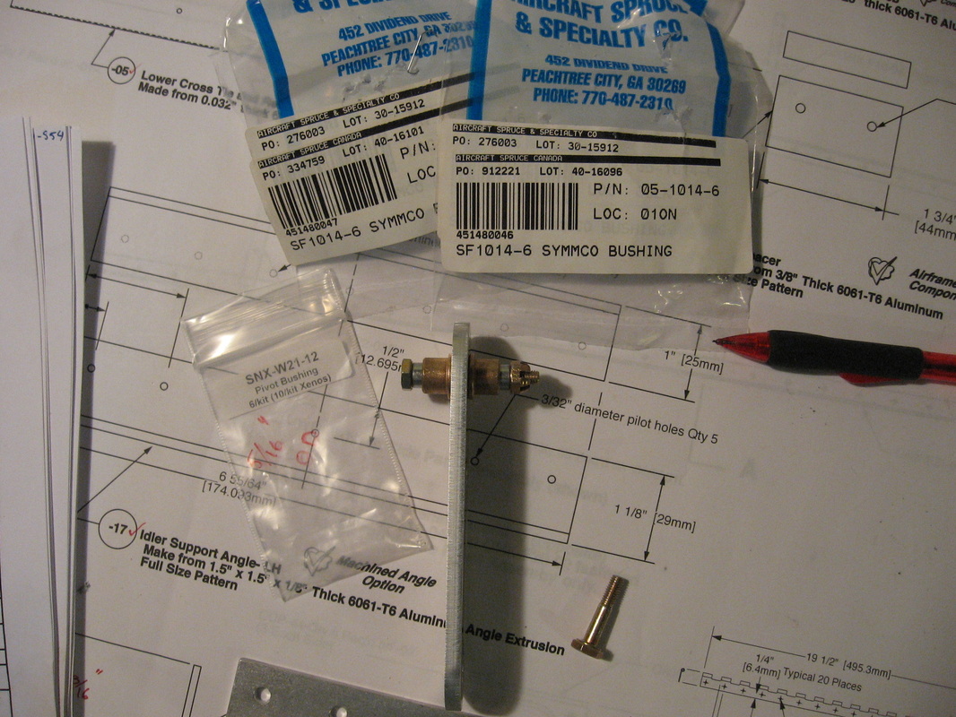
The following clarifies the 2 types of bushings used here.
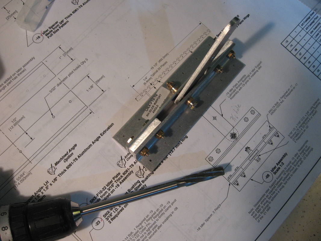
And the completed assembly below.I used a 7/16" reamer(shown) to line ream the holes to make the bronze bushings fit.This one will require very thin paper shims between angle irons and spacers to achieve a not so snug fit.
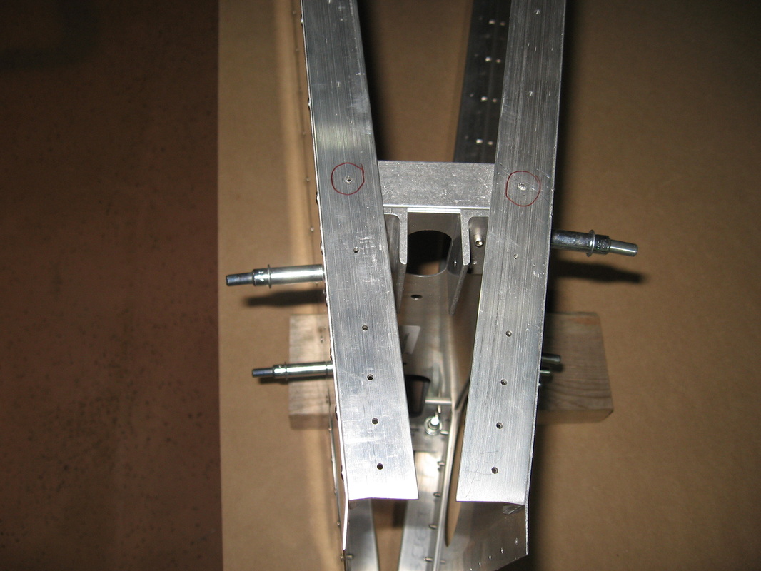
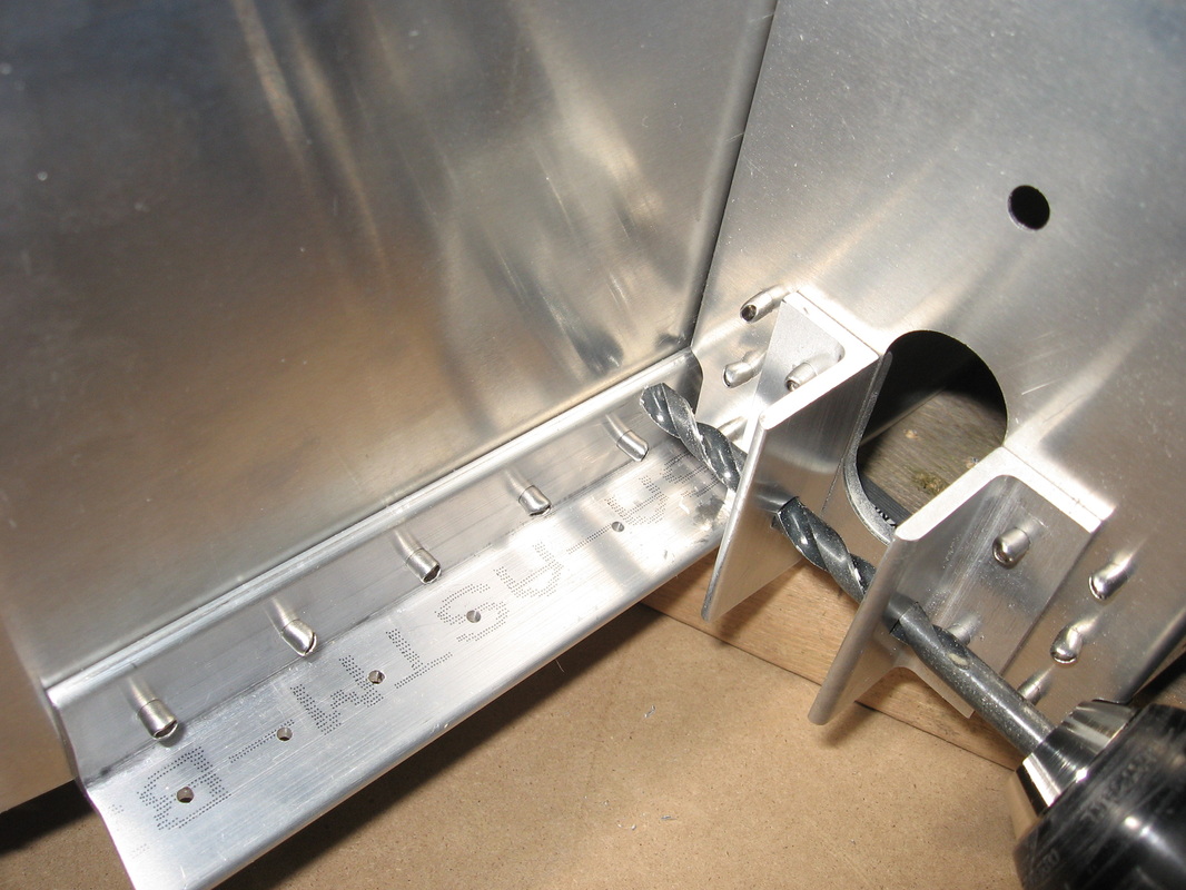
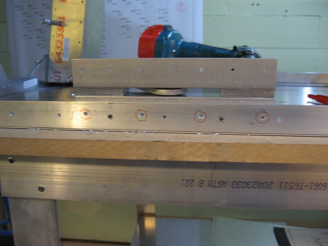
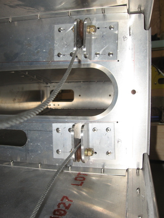
(Note ;see revision for moving idler)Below is how I will attach the idler assembly to the lower longeron. After positioning it 9 3/8"(see the new revision for this dimension) from the end(measured from the longest point),the 4 red circled holes were drilled down from the idler using 4 holes in the idler angle iron.The 3 holes in between were drilled up from the longeron so that when the bottom finally gets attached all I will have to do is drill down through the bottom panel at the 4 circled holes and then rivet all 7 holes.
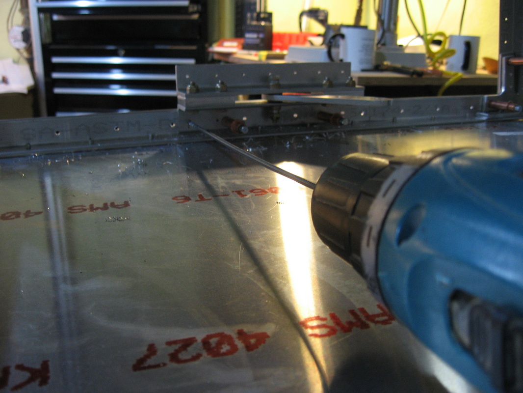
Below.Drilling down from the idler through the longeron using a 12" drill bit so that the hole would be square to the longeron .Using a bit any shorter and the holes will go in at an angle(please note that the idler is in the pre-revision location.When I get around to moving it I will retake the picture and post it here.
F22 to F17 complete including all rivets called for,all bolts and nuts called out were put in and tightened.I also installed the seat belt bracket after drilling them for a 3/8" bolts(note the revision on the location change)
|
|
I purchased the shoulder harness extension from Air Ward as can be seen in the two photos above.A good deal. www.airward.com AMELIA Search Engine
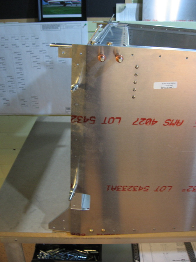
Just a heads up on the vertical row of rivets seen here beside the sticker.I wound up drilling out the top one to facilitate getting the turtle deck skin under the side skins so you might want to leave it out.
F-15
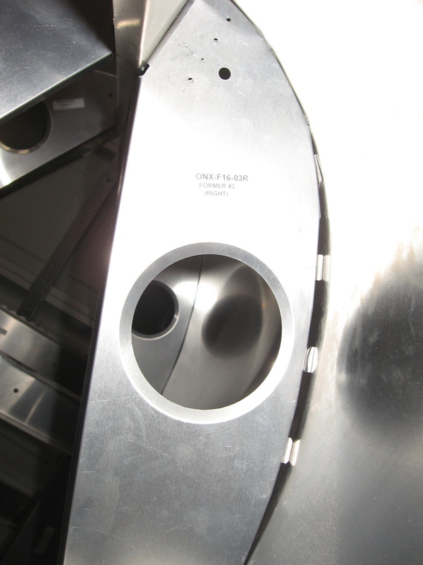
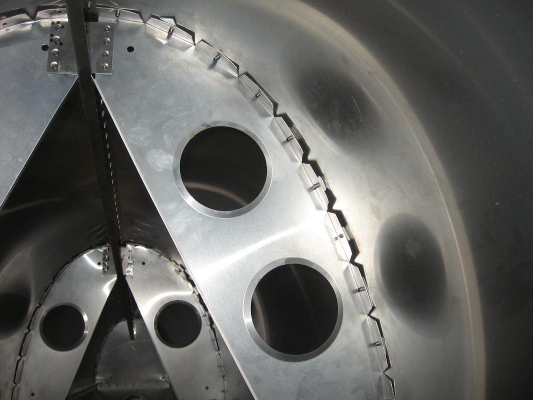
According to the instructions for assembly on page f-15 the formers should be pushed into position after clecoing the skins to the spline and the spline with the skins is then placed over the fuse and the lower skin is clecoed to the longerons.Problem is I could not get the #3 formers to fit properly.After talking with Kerry at Sonex and explaining what I had tried I showed Kerry these spacers that I used to fill the void which he said would be alright.
My #1 and #2 formers fit perfectly and my #4 bulkhead fits nicely when these spacers are used at #3.I started a discussion on the forums and it turns out i am not alone.Some didn't care and just riveted anyway with the resulting dimples in the skin.Other e-mailed and said they had no problems with the fit at any of the formers.I believe that all kits were not created equal.The above was my solution and I am happy with it,though I plan to make the spacers longer.They are presently 1/2" X 1/2" ( see below).
I should mention that Kerry told me that they might eliminate the pre punched holes in the formers so that they can be more easily positioned ,as, the holes at the bottom of the formers are what prevented me from getting the former in position though I can say that it really made no difference when I ignored the prepunched holes and still could not get #3 to fit.I will of course use CCp 44's where the spacers are located.
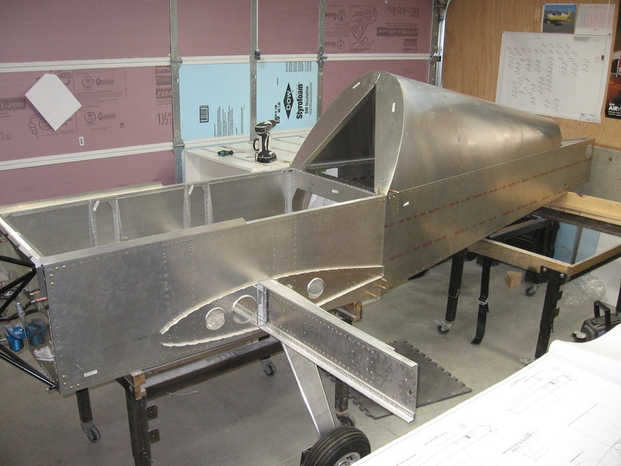
Skins removed and everything up- drilled ,deburred and the formers riveted in place.I substituted CCP44's at the bottom of the #1 formers as I considered the 42's a bit short here.
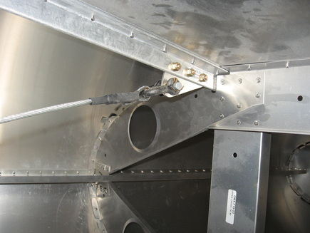
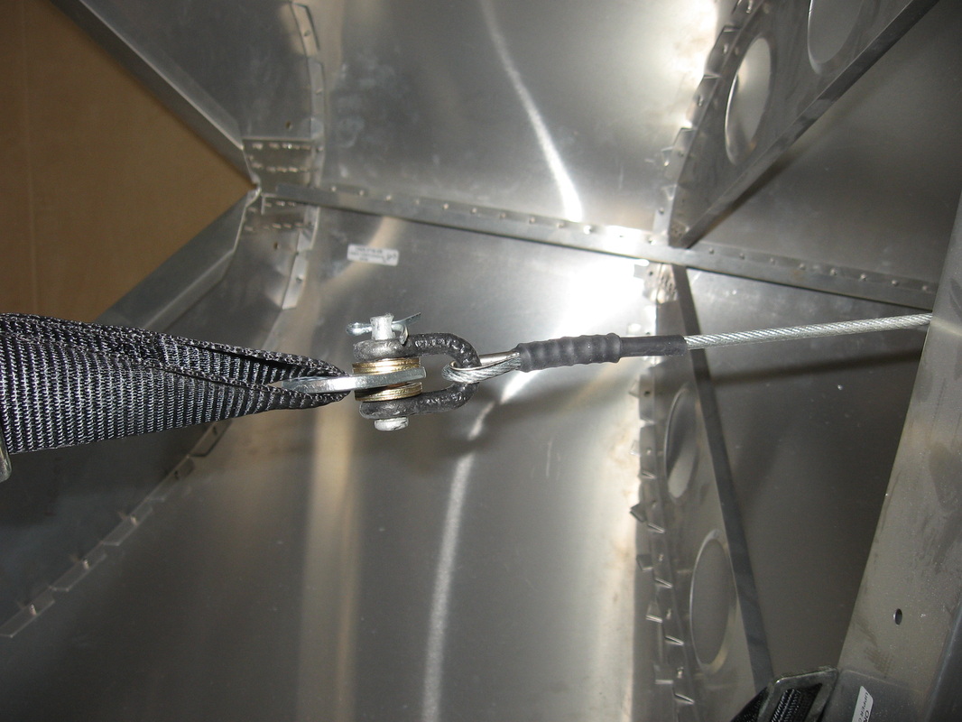
Before closing up the turtle deck I am going to place the brackets for the rudder pulleys at the #4 bulkhead as it will be a bit easier to do though there would be no real problem to do it afterwards.
Before closing up the turtle deck I am going to place the brackets for the rudder pulleys at the #4 bulkhead as it will be a bit easier to do though there would be no real problem to do it afterwards.

Just under 2 oz.extra weight for making the brackets this way.Saving time.Priceless.
As can be seen I did not make the brackets as per plans.Where they call out a 1" wide space in which to attach the pulleys I made it 1 1/8" wide.You can make it 1" but ignore the dimension for the bolt hole as if you center it on the 1" as in the plans you will find that the pulley wheel will rub against the bulkhead and not turn freely.This would appear obvious if you think about it using the 1" pulleys supplied.(been there done that) I simply made it wider to give lots of clearance.Also I didn't bother to shape the brackets as per plans.Just seemed like a waste of time and the extra weight I can live with.
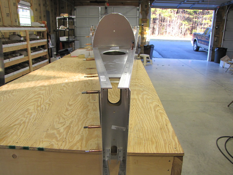
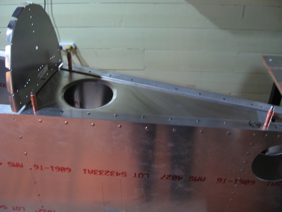
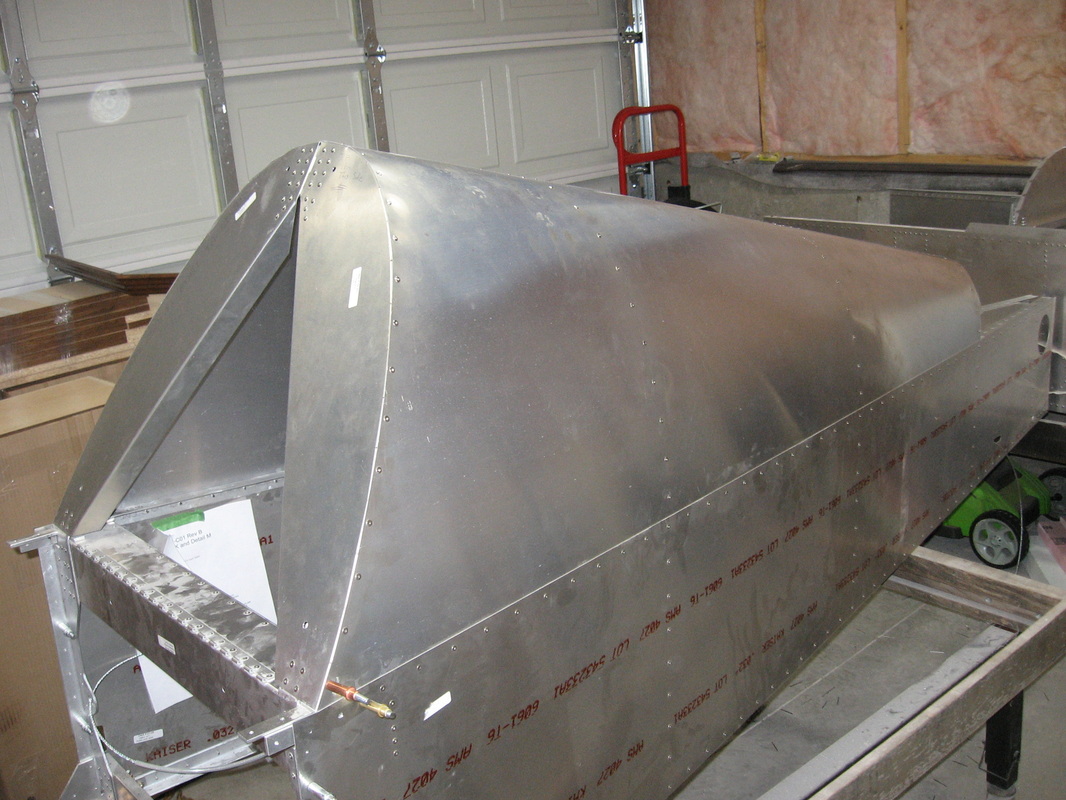
F-14 TAIL CONE ASSEMBLY
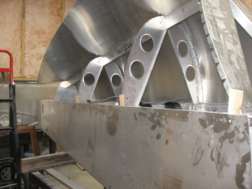
After Clecoing the skins to the spline I used shims at the bulkhead positions to facilitate getting the skins to slip under the side skins.
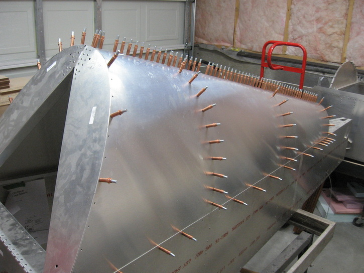
You will find that the skins slip under quite easily if you start at the front and work back getting the skin behind the shims.Note in the above photo the shims I used to fill out the skins.I used ccp44's for the wider shims.
North meets South