
ONX-L01
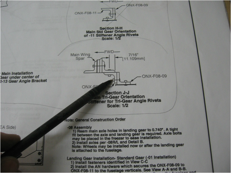
Main Landing Gear Details and Installation
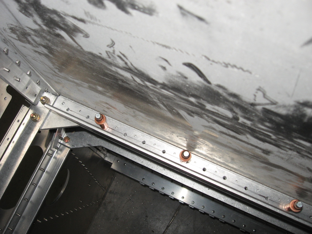
The predrilled holes on the gear stiffener ONX-F08-11 are to close to the edge as shown in the drawing, and when you transfer them to the Gear Attach Angle the holes are too close to the bend in my opinion so I re-drilled a row of holes closer to the centre as can be seen in the picture,then transferred the holes to the attach angle.
Locating the landing gear Nov 24/13
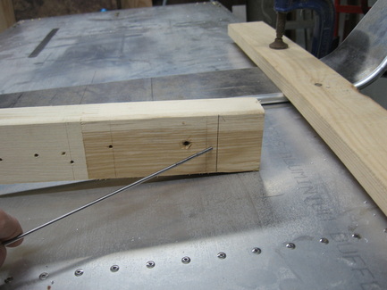
I have seen various methods of locating the centre of the gear and here's mine.
Get a board about 2' or a bit longer and make sure the two ends are square,then draw a perpendicular line near one end.
I have seen various methods of locating the centre of the gear and here's mine.
Get a board about 2' or a bit longer and make sure the two ends are square,then draw a perpendicular line near one end.
Then place the board so the drawn line lines up with the left side edge of the gear.Then…….
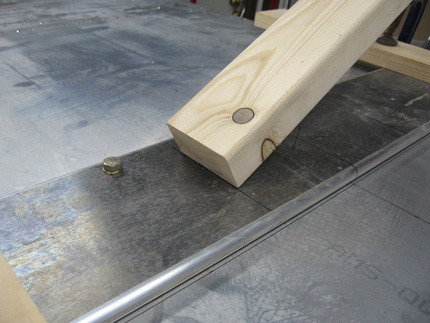
make a small mark where the other end contacts the gear,then using a square make a line.
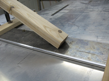
Do the same on the other side,using a square to make the second line
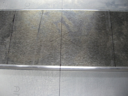
It is now easy to find the centre of the gear.Transfer the centre line to the sides of the gear .Locate the centre of the fuselage bottom and now you have the longitudinal .
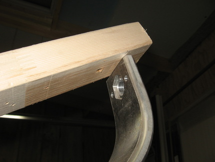
The gear is 5" wide and the centres of the gear angle brackets are 3 1/2" apart which leaves 3/4" overhang on either side of of those rivet lines.
For me the aft edge of the gear was 19 1/16" from the aft edge of the fuse bottom.
The gear is 5" wide and the centres of the gear angle brackets are 3 1/2" apart which leaves 3/4" overhang on either side of of those rivet lines.
For me the aft edge of the gear was 19 1/16" from the aft edge of the fuse bottom.
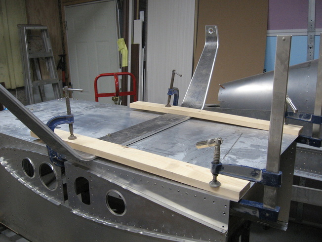
Clamp the gear in place double checking squareness (19 1/16" distance from aft edge)
Get under neath and drill up using the holes in the gear angle brackets.
I up drilled to 1/4" from below and then up drilled to the 5/16" from above.
For the four holes at the edge I used a 12" 1/8" bit and up drilled to 5/16" from the top side.
Get under neath and drill up using the holes in the gear angle brackets.
I up drilled to 1/4" from below and then up drilled to the 5/16" from above.
For the four holes at the edge I used a 12" 1/8" bit and up drilled to 5/16" from the top side.
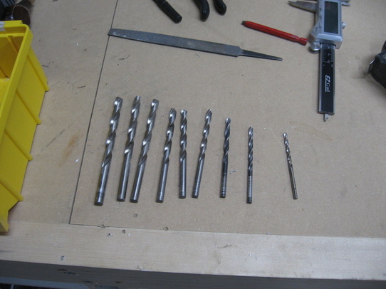
These are the bits I used to get to the final size .
Not shown is the 12 inch 1/8" bit needed for the four holes near the edge.
Not shown is the 12 inch 1/8" bit needed for the four holes near the edge.