Wings
ONX-W23,22
No assemblies on these 2 pages
ONX-W21
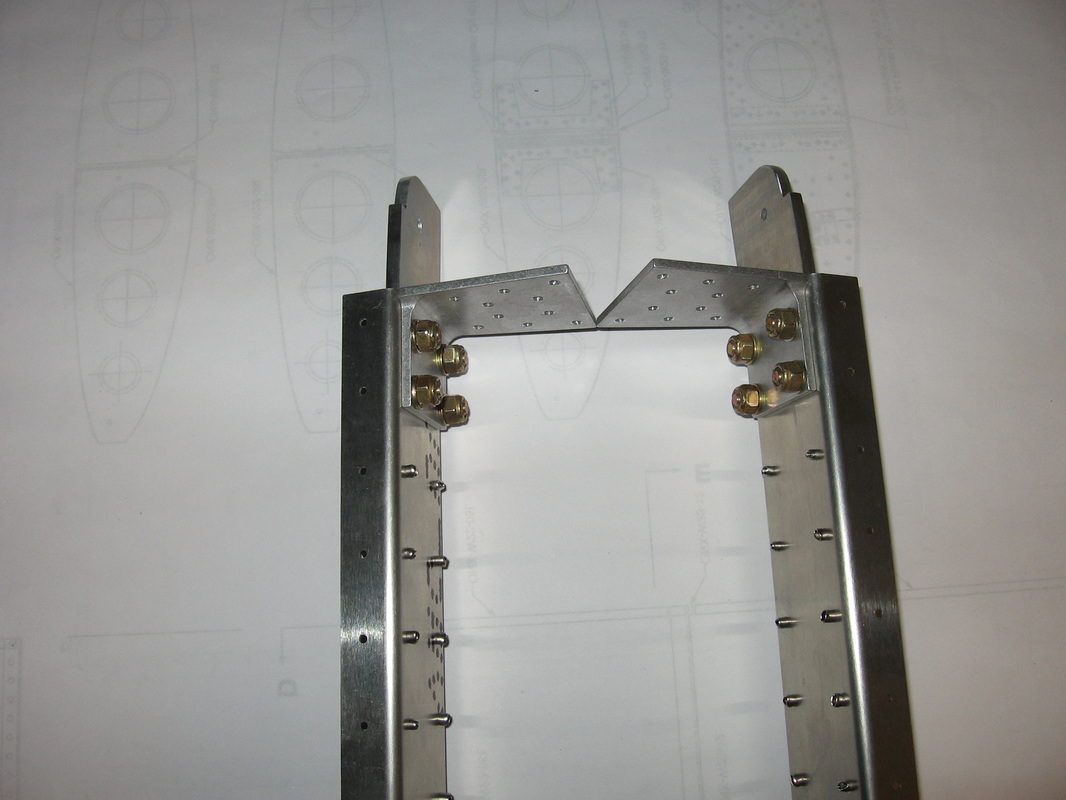
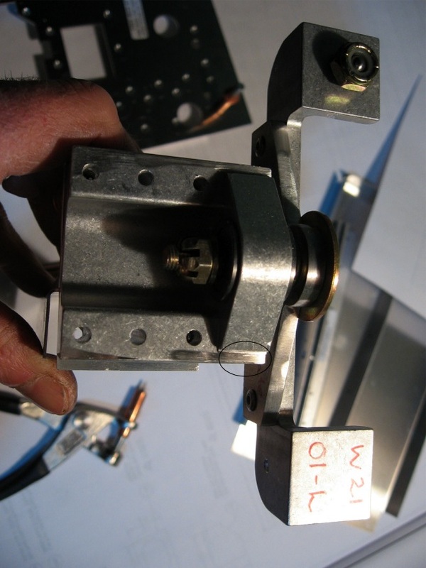
A revision points out that some will have 2 aileron bellcrank paddles that are drilled and tapped on the same side (if you bought the machined angle parts)Mine was one of them so as can be seen I drilled and tapped the left side here .Drill size for the tap is 17/64".Tap size is listed on the drawing
Problems with wing fold and solutions by Rheal
Onex Build Status and Completion Photos Click on link and go to page 4 and 5
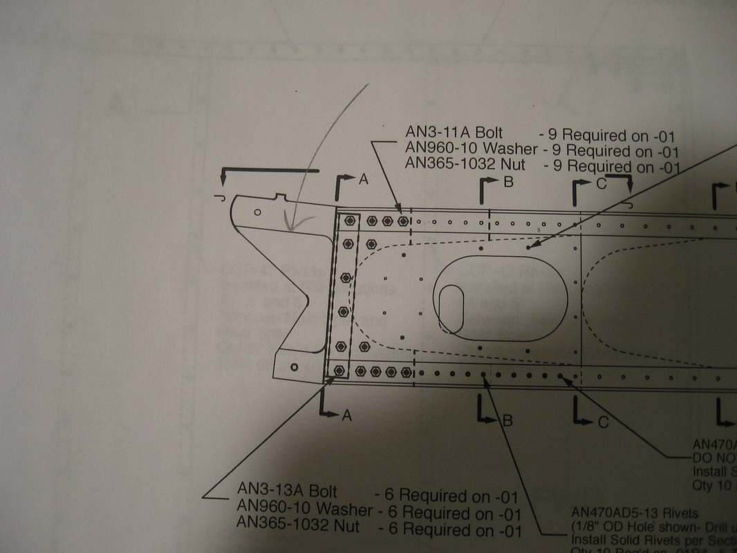
I have annotated the Sonex recommended assembly below. This is how I would do it if I was to built another Onex:
Note: General Construction Order for -01 Wing Spar Join and Fold Installation
This is an extremely critical assembly procedure! Exact reamers must be used
to ensure tight hole tolerances. Jeremy's recommended concentricity is .003 in.
SPECIAL TOOLS REQUIRED:
"U" Letter Drill (0.3680")
0.3730" OD Reamer (Qty 1) for Main Spar Pivot Hole
0.3760" OD Reamer (Qty 1) for Main Spar Lower and Rear Spar Attach Holes
Note: Measure AN6-14 Bolts for Main Spar Pivot holes with a micrometer.
These should measure between 0.3715 and 0.3720 for 0.3730 Reamer to be used.
Smaller Reamer may be required if bolts are smaller.
MAIN SPAR JOINT:
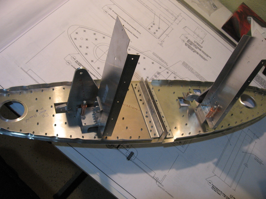
1) Slide ONX-W02-01L Outboard Wing Panel into inboard wing structure. The Inboard wing outboard ribs should not be installed in order to drill perpendicular. Actually, if the Outboard spar ribs are not installed yes you could lay the 2 spars flat and drill with the press drill. Remember that the main spar should butt the interior sides of the sandwiched aluminum plates to ensure to mimic the same position when the wing is rotated down. The wing weight will naturally force the mechanism to butt together. This is very important otherwise it is going to be very hard to have the locking pin to penetrate if they are misaligned like mine are on the LH (see previous email).
2) Insert 1/4" Pin or Bolt in Main Spar Pivot Hole identified in View A-A. (A 1/4" Drill
may be needed to run through the assembly to allow bolt to be installed).
3) Up-drill Rear spar attach pin hole to 1/4" per View C-C. This has to be done with the spars installed on the FWD box.
4) Insert 1/4" Pin or Bolt into Rear spar attach pin hole per View C-C.
5) Drill thru Main Spar Lower Attach Hole with "U" Letter Drill (0.3680").Do not install the guiding block yet if drilled from the FWD position. If drilled from the AFT it is OK. This important to stay perpendicular to the spar axis. Otherwise the lever guiding slot will be misaligned.
Note: Drill as SLOW as you can and use plenty of DRILLING LUBRICANT.
6) Ream the same lower attach hole to 0.3760" OD.The black guiding block should be in place now.
7) Insert Main Spar Pin into lower attach hole per View A-A.Stop here if not perfectly perpendicular and snug fit.
8) Remove 1/4" temporary Pin or Bolt from Upper attach location and make sure
outboard wing is supported so upper hole alignment is maintained.
9) Up-drill Main Spar Pivot Hole to "U" Letter Drill (0.3680") per View A-A.
10) Ream the same pivot hole to 0.3730" OD.
11) Insert AN6 Bolt in this location per View A-A.
REAR SPAR:
1) Remove temporary 1/4" Pin or Bolt from rear spar.
2) Drill thr rear spar attach hole with "U" Letter Drill (0.3680").
3) Ream the same attach hole to 0.3760" OD.
4) Insert Rear Spar Pin into this location and ensure smooth motion.
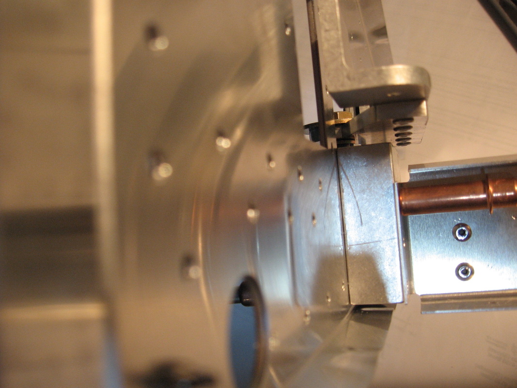
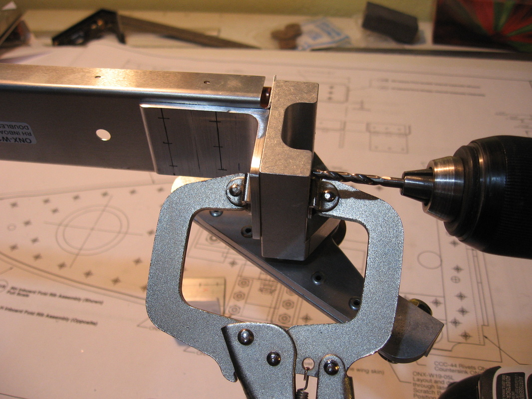
As you can see, you can do the main spars on the press drill but you won't be able to drill the rear spar because the wing has to be in place to ensure the whole assembly is square and perpendicular. The only way to achieve this is to have the Outboard wing skins on and the Inboard wing outboard ribs installed (obviously no Inboard skins necessary at this stage). In summary, the main spar drilling can be done without any ribs installed at all and without being mounted on the fuselage. The important reference is the internal butting interface surface (sandwiched between the steel plates see picture below where my vernier is touching) being respected when drilling the 2 holes. For the rear spar, everything has to be assembled in place with the main spar locked and then it is easy to drill the rear from AFT without errors. Hoping this will help you to better understand the issues.
DSCF1302sm.jpg (116.86 KiB) Viewed 2 timesRheal
ONEX plans 0021Onex11 Posts: 21Joined: Thu Jun 02, 2011 7:01 pmLocation: Saint-Hyacinthe, Quebec, Canada
I have annotated the Sonex recommended assembly below. This is how I would do it if I was to built another Onex:
Note: General Construction Order for -01 Wing Spar Join and Fold Installation
This is an extremely critical assembly procedure! Exact reamers must be used
to ensure tight hole tolerances. Jeremy's recommended concentricity is .003 in.
SPECIAL TOOLS REQUIRED:
"U" Letter Drill (0.3680")
0.3730" OD Reamer (Qty 1) for Main Spar Pivot Hole
0.3760" OD Reamer (Qty 1) for Main Spar Lower and Rear Spar Attach Holes
Note: Measure AN6-14 Bolts for Main Spar Pivot holes with a micrometer.
These should measure between 0.3715 and 0.3720 for 0.3730 Reamer to be used.
Smaller Reamer may be required if bolts are smaller.
MAIN SPAR JOINT:
1) Slide ONX-W02-01L Outboard Wing Panel into inboard wing structure. The Inboard wing outboard ribs should not be installed in order to drill perpendicular. Actually, if the Outboard spar ribs are not installed yes you could lay the 2 spars flat and drill with the press drill. Remember that the main spar should butt the interior sides of the sandwiched aluminum plates to ensure to mimic the same position when the wing is rotated down. The wing weight will naturally force the mechanism to butt together. This is very important otherwise it is going to be very hard to have the locking pin to penetrate if they are misaligned like mine are on the LH (see previous email).
2) Insert 1/4" Pin or Bolt in Main Spar Pivot Hole identified in View A-A. (A 1/4" Drill
may be needed to run through the assembly to allow bolt to be installed).
3) Up-drill Rear spar attach pin hole to 1/4" per View C-C. This has to be done with the spars installed on the FWD box.
4) Insert 1/4" Pin or Bolt into Rear spar attach pin hole per View C-C.
5) Drill thru Main Spar Lower Attach Hole with "U" Letter Drill (0.3680").Do not install the guiding block yet if drilled from the FWD position. If drilled from the AFT it is OK. This important to stay perpendicular to the spar axis. Otherwise the lever guiding slot will be misaligned.
Note: Drill as SLOW as you can and use plenty of DRILLING LUBRICANT.
6) Ream the same lower attach hole to 0.3760" OD.The black guiding block should be in place now.
7) Insert Main Spar Pin into lower attach hole per View A-A.Stop here if not perfectly perpendicular and snug fit.
8) Remove 1/4" temporary Pin or Bolt from Upper attach location and make sure
outboard wing is supported so upper hole alignment is maintained.
9) Up-drill Main Spar Pivot Hole to "U" Letter Drill (0.3680") per View A-A.
10) Ream the same pivot hole to 0.3730" OD.
11) Insert AN6 Bolt in this location per View A-A.
REAR SPAR:
1) Remove temporary 1/4" Pin or Bolt from rear spar.
2) Drill thr rear spar attach hole with "U" Letter Drill (0.3680").
3) Ream the same attach hole to 0.3760" OD.
4) Insert Rear Spar Pin into this location and ensure smooth motion.
As you can see, you can do the main spars on the press drill but you won't be able to drill the rear spar because the wing has to be in place to ensure the whole assembly is square and perpendicular. The only way to achieve this is to have the Outboard wing skins on and the Inboard wing outboard ribs installed (obviously no Inboard skins necessary at this stage). In summary, the main spar drilling can be done without any ribs installed at all and without being mounted on the fuselage. The important reference is the internal butting interface surface (sandwiched between the steel plates see picture below where my vernier is touching) being respected when drilling the 2 holes. For the rear spar, everything has to be assembled in place with the main spar locked and then it is easy to drill the rear from AFT without errors. Hoping this will help you to better understand the issues.
DSCF1302sm.jpg (116.86 KiB) Viewed 2 timesRheal
ONEX plans 0021Onex11 Posts: 21Joined: Thu Jun 02, 2011 7:01 pmLocation: Saint-Hyacinthe, Quebec, Canada
ONX-W21 Aileron Bellcrank assembly
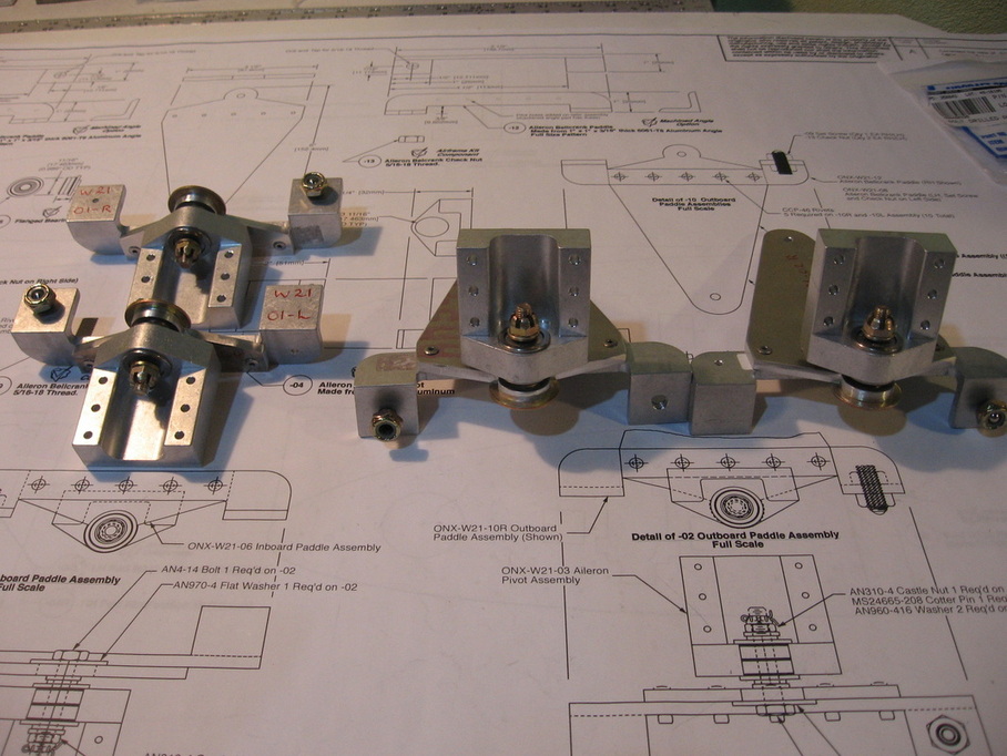
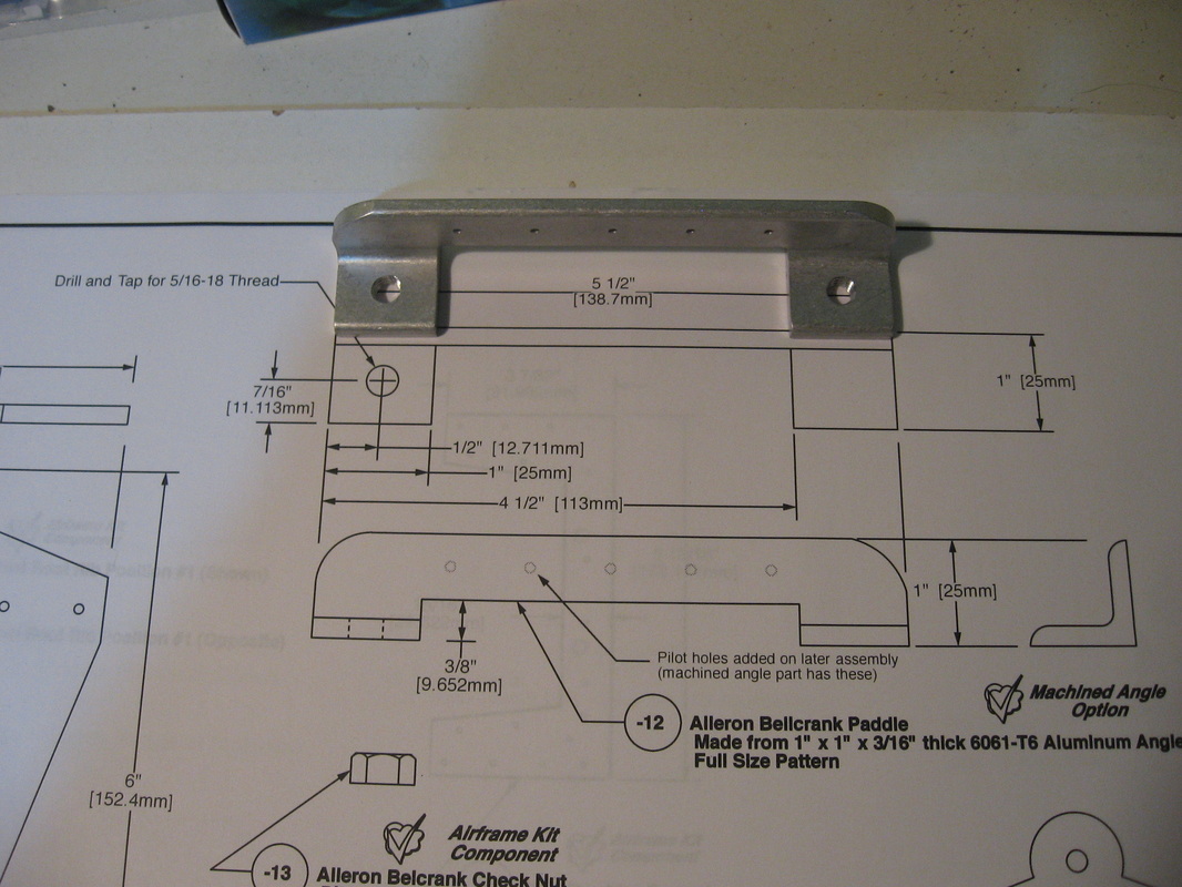
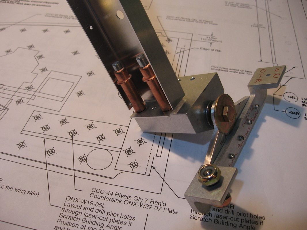
As can be seen above I have assembled the Aileron Inboard and Outboard Paddles.Made sure to eliminate the stress risers along the edges.I had a reamer turned to the size given on the drawing to open the holes to accept the flanged bushings(I had tried the oven and freezer method but only managed to destroy one bushing-$12 each by the way) .One was not a tight fit (the bushings just fell in but had no play) and Kerry told me this would not be a problem.I have not put the cotter pins in yet.
ONX-W-20 and 19
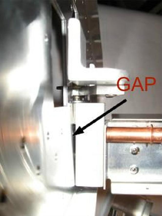
A revision deals with the fact that the Bellcrank Pivot does not sit flush with the rib as can be seen here.You have a choise of cutting the rib and doubler to allow it to sit flat or notch the Bellcrank pivot.I chose the latter
You can see the notches I made here.All 4 Bellcrank pivots will be done the same way.
After notching
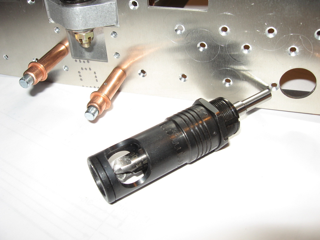
Here is the micro countersink tool I used for the doublers.Works great . http://www.aircraftspruce.ca/catalog/topages/at441.php
Attaching Pivot Doubler Angle to RH Inboard Pivot Doubler Channel
Cleco Channel to Bellcrank Pivot.This will help align the Pivot Doubler angle
Clamp Pivot Doubler Angle to Bellcrank Pivot ,using it as a template to start the holes in the angle plate. Remove, drill through ,re-attach with 2 cleco's and start third hole.Remove finish last hole and debur.After locating the 6 holes in the Angle and drilling up to 1/8" re-attach the angle to bellcrank pivot and drill through the channel.
Rivet angle to channel.
Rivet angle to channel.
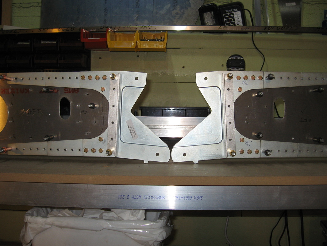
Here are the left hand inboard(bottom) and outboard ribs in their proper relation to each other in the wing up position
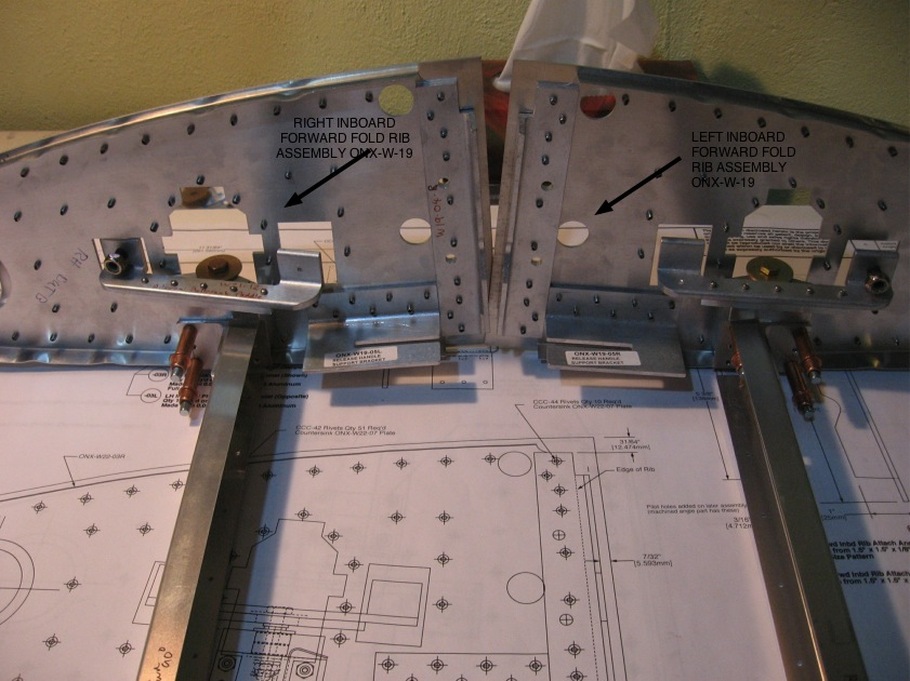
Righthand OUTBOARD FOLD RIB ASSEMBLY on left
ONX-W20
ONX-W20
Right hand OUTBOARD FOLD RIB ASSEMBLY on left
ONX-W20
ONX-W20
ONX-W15 INBOARD REAR SPAR ASSEMBLY
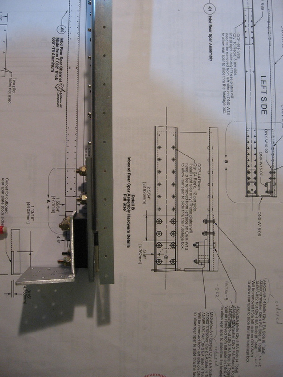
No problems here.Just remember to check the revision notes.
ONX-W14 WING FOLD PIN ASSEMBLY
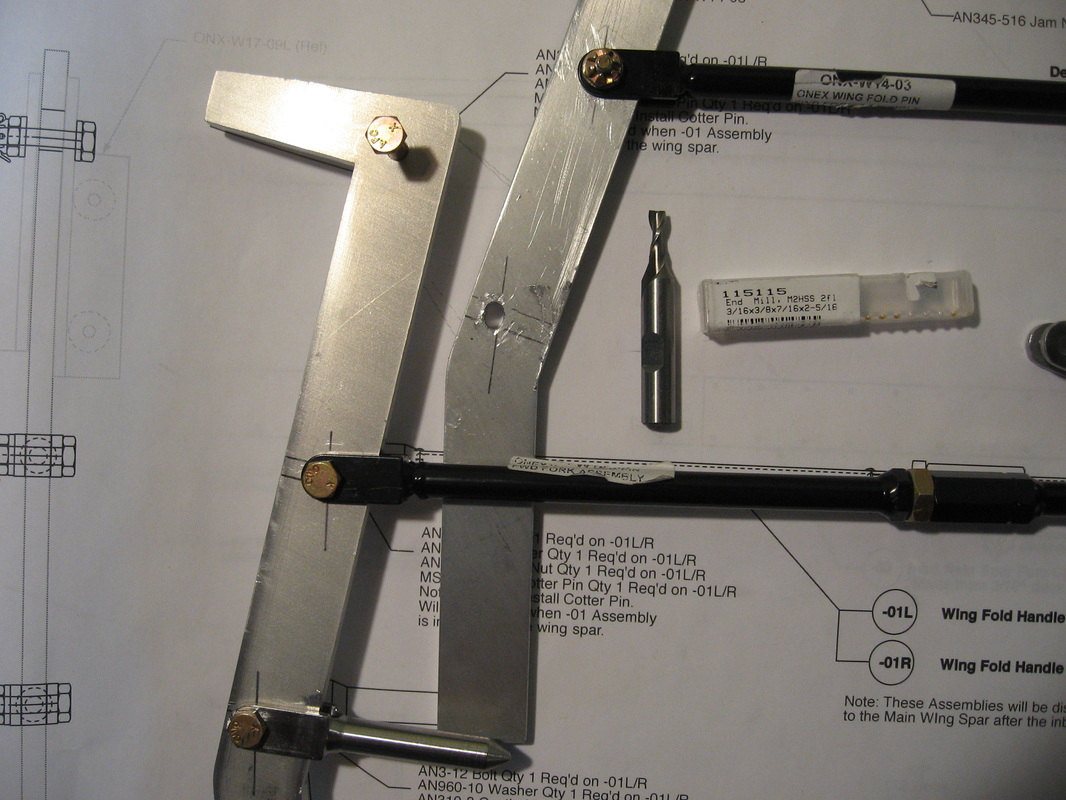
Your supposed to make 2 slots at these 2 locations.The only way I could think of to accomplish this was to go out and buy the 3/16" end mill cutter you see here and chuck it in my drill press.Clamping a board on the table and aligning it with the direction the slot was ,I was able to make a neat and tidy slot as shown here.I of course marked it out first.
The only other issue is drilling the pin to 3/16"..IT'S STAINLESS STEEL SO START UP DRILLING WITH BRAND SPANKING NEW BITS AND DRILL SLOW AND WITH EVEN PRESSURE AND DON'T LET UP ONCE IT STARTS CUTTING.IF YOU DRILL AT TOO HIGH A SPEED IT WILL WORK HARDEN IN A HEART BEAT AND THEN NO AMOUNT OF DRILLING WILL MAKE IT WORK.I new this and drilled the first one no problem.Up drilling one size at a time.The second I wasn't so lucky.I wound up turning the metal blue trying to get it to drill through and once that happened I considered it garbage and ordered a new one.Not cheap......$47 for the part.Ouch.
I will mention it now ahead of time that when you are updrilling 4130 it's the same problem.The outboard spars have some thick 4130 to drill.
Same method is used .Sharp drill ,slow speed and lots of even pressure.
I have purchased a drill bit sharpener and it is turning into a great purchase.As soon as I feel a bit is getting dull I throw it in the drill sharpener. http://www.canadiantire.ca/browse/product_detail.jsp?PRODUCT%3C%3Eprd_id=845524443340638&FOLDER%3C%3Efolder_id=1408474396672926&bmUID=1361140571654 this is the one I bought.Easy to use and takes about 1 min.
ONX-W11 OUTBOARD MAIN SPAR ASSEMBLY
THIS LINE SHOULD BE A HIDDEN LINE
IE; IT IS COMPLETELY FLAT IN THIS VIEW,THE INDENT IS FACING AFT
When you lay out the pieces remember that the view shown above is wrong.The line shown by the arrow should be a hidden line.
The photo (top) shows the spar completely up drilled and debured, as it would be seen from the rear of the plane. Careful drilling the thick 4130 steel.Slow and even pressure with sharp drill bits as you up drill.High speed will result in work hardened steel .I updrilled the rib locations to 1/8" now even though it is not called for.
that way you can debur these holes.I don't know that it matters but I am confident enough now that the matched holes are perfect so why not do it now.
ONX-W10 OUTBOARD REAR SPAR ASSEMBLY