
ONX-F13
Download the PDF from the revisions page
ONX-F12
Parts page nothing to do here- no revisions
ONX-F11
Download revision PDF to correct windshield Bow attach angle holes,and drill new holes now if needed on your parts.
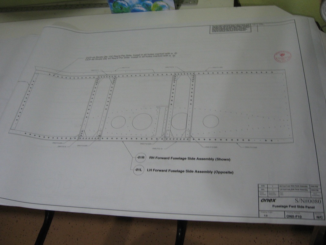
ONX-F10
FWD side panel assembly.
Keep an eye out for holes that don't get riveted yet and which holes require CCP 46 rivets.No revisions for this page.
Keep an eye out for holes that don't get riveted yet and which holes require CCP 46 rivets.No revisions for this page.
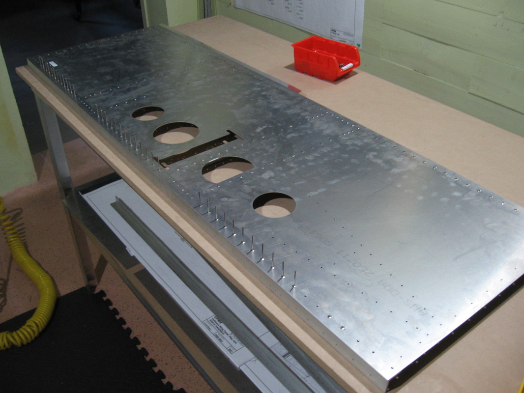
This is where my in-out debur tool really shines.Lots of holes
ONX-F09
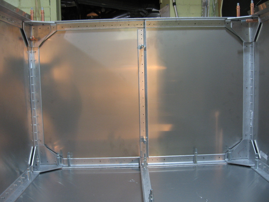
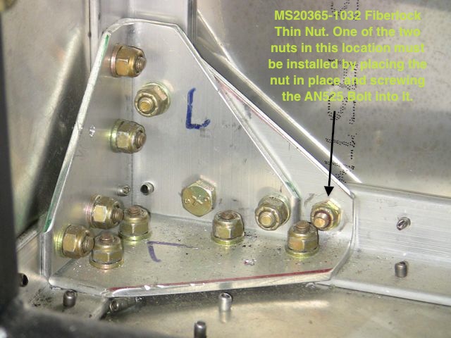
A few pic's to sort out the all those corner brackets.
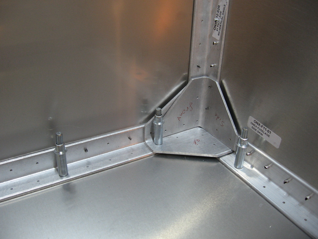
Lower right detail
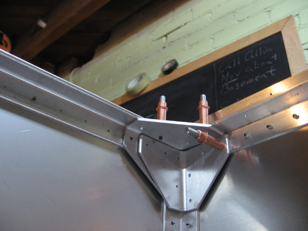
Upper right detail
From the revisions page
Note that all of these brackets required lots of chamfering to make them sit in the correct location due to the curved corners that they had to sit against.I use a scotch brite wheel on my bench grinder which does a nice job of rounding the corners .
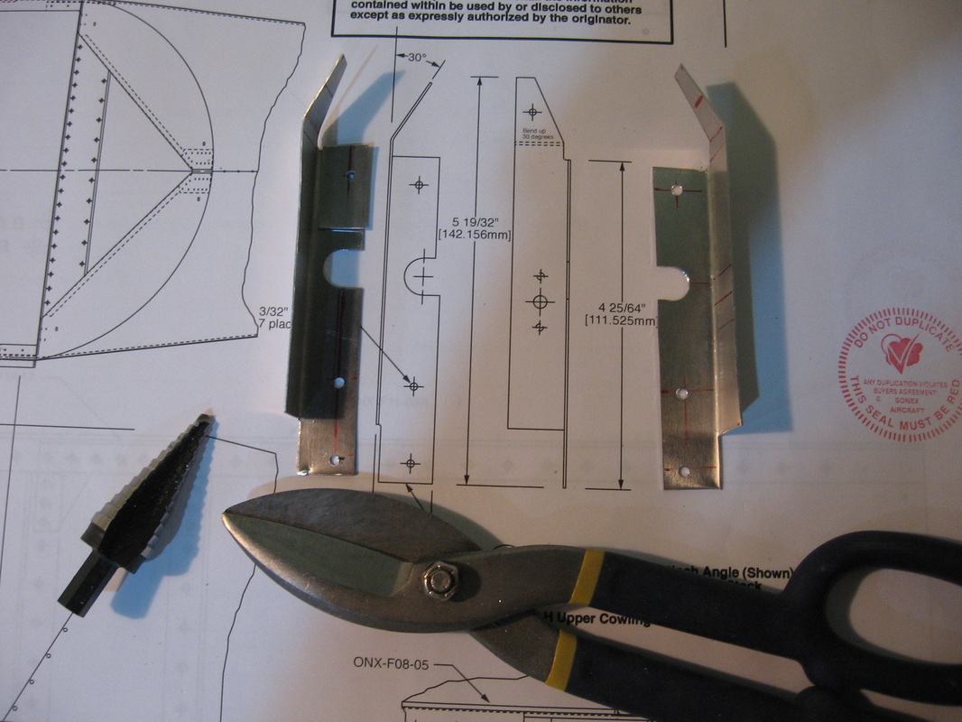
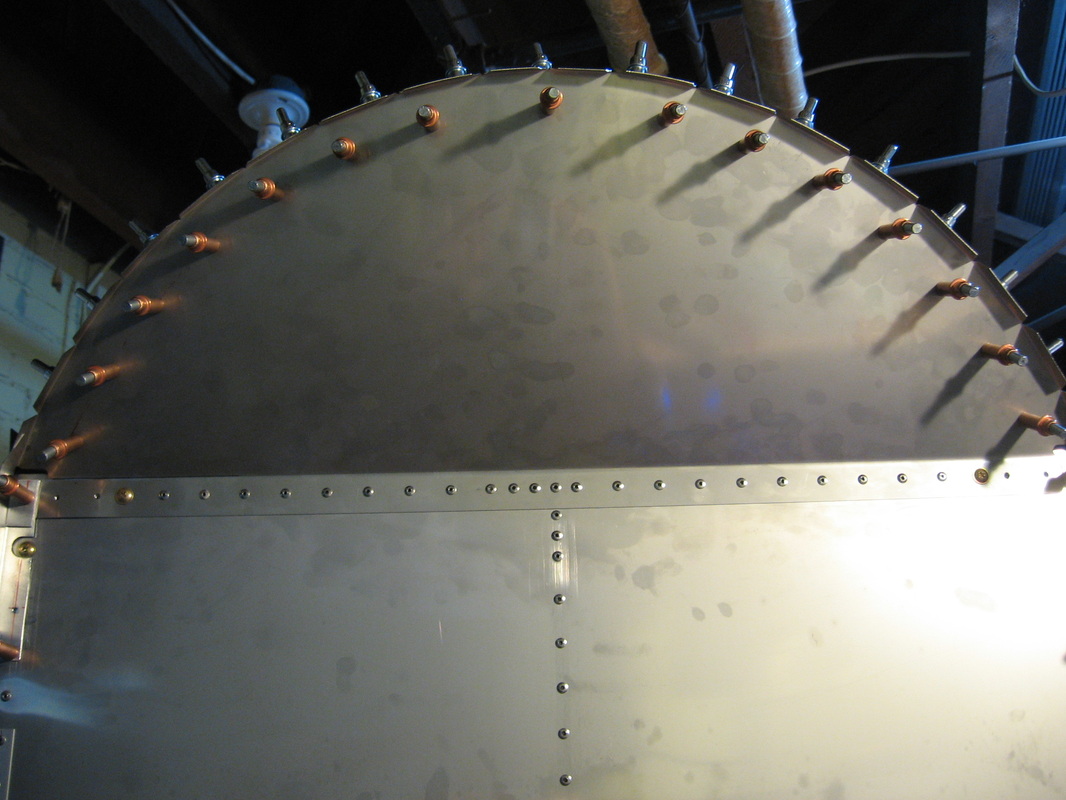
Upper Cowling Attach Angles
and the tools I used to make them
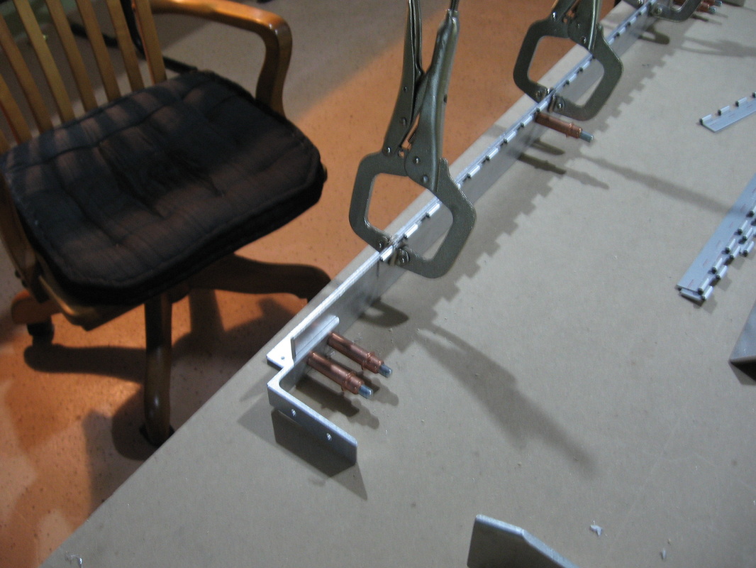
For attaching to the firewall I only drilled the top hole in the angle ,then klecoed that one hole ,clamped the bottom in place and drilled from the inside to locate the other 2 holes.
In Place
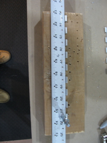
Cowl attach hinges
Using my aluminum rule jig to drill 3/32" holes
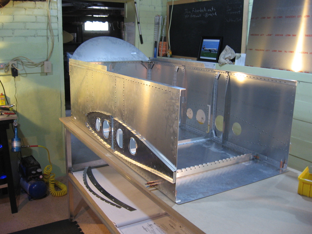
Everything complete from page F09 except joining the aft fuse which I can't do till it moves to bigger quarters. Over all this page gave some challenging assembly.Those corner brackets are not plug and go.They have to be finessed into place so the holes all line up.
Things to be careful about.
1) Tighten down all the bolts on those corner brackets before putting any rivets in that immediate area.
2) make sure the metal shavings are cleaned out before tightening them down
getting small particles between the skin and brackets will cause you grief.
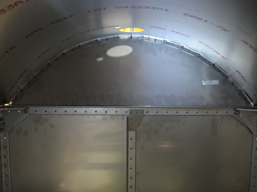
3)Check the angle of the upper firewall former that it is 30* per plans.(mine was 40*)
5)Mark all holes that don't get a rivet before you start riveting.
6) Up drill your bolt holes in stages.Don't go from 1/8 to 3/16 in one go. Drill an intermediate before the final 3/16 th's
7) You should still be having fun :)
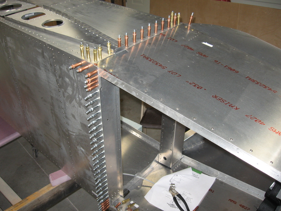
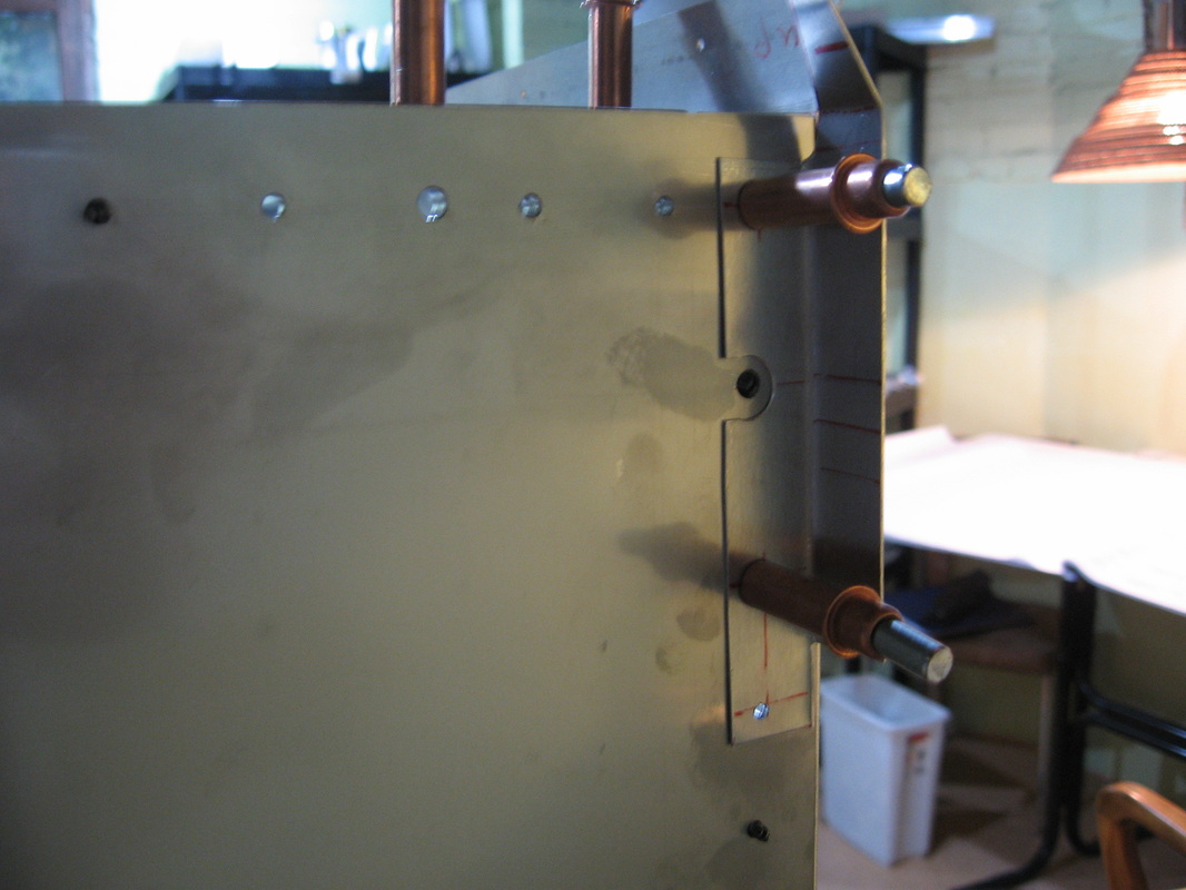
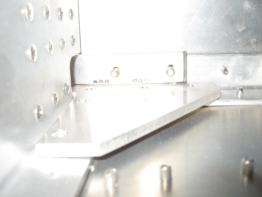
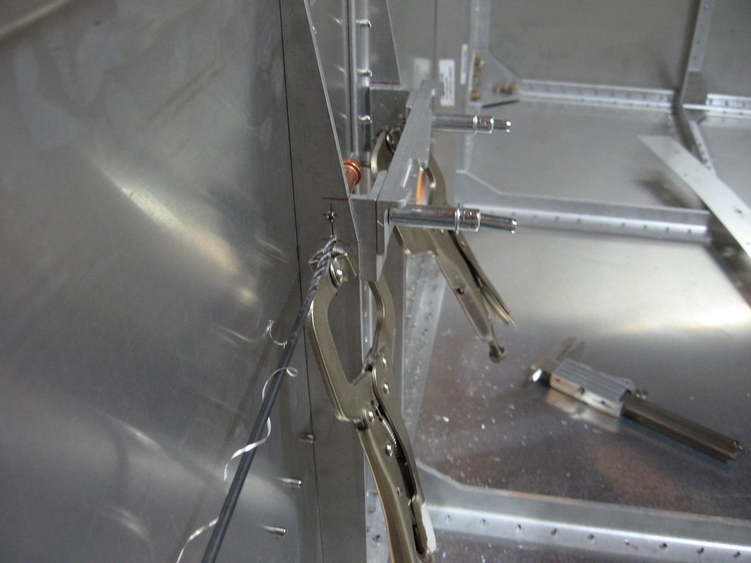
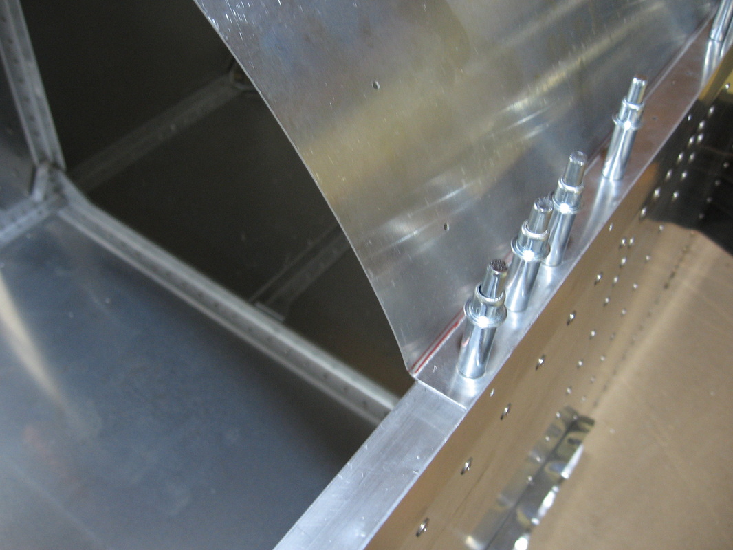
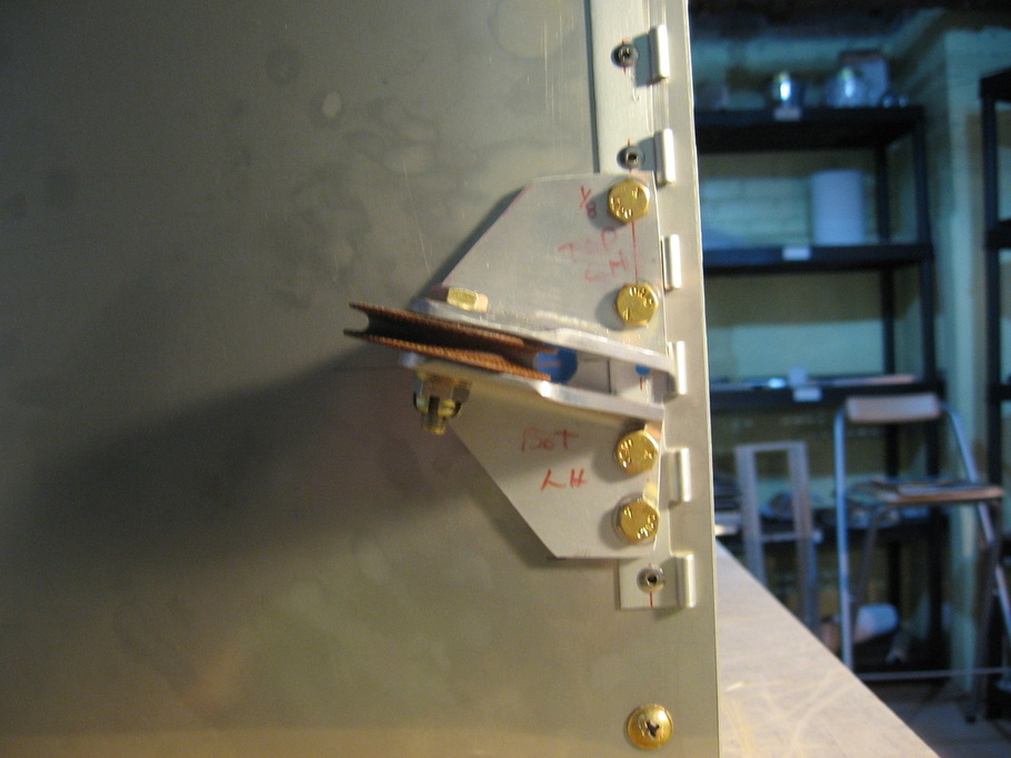
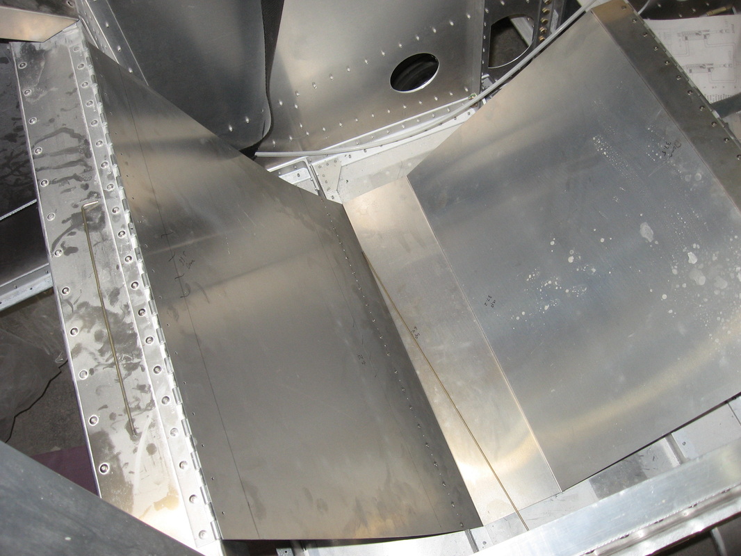
Test run to see how the two halves fit together.Had a few alignment problems on the lower corner brackets(gold clecos) at the sides.In the photo below you can see the misalignment .Those are the bolts in the drilled holes and you can see the original holes in the bracket just peeking above the through holes
Seat attach assembly from page F08
ONX F05
Bending the glare shield on my metal brake
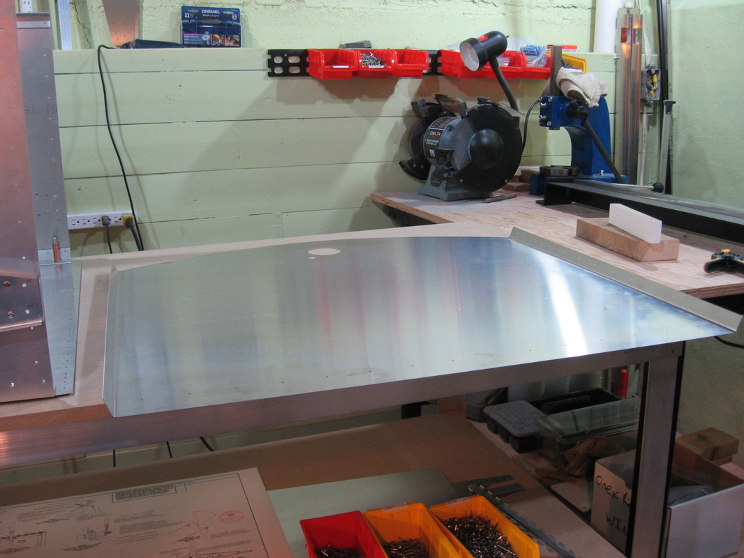
Glare shield ready
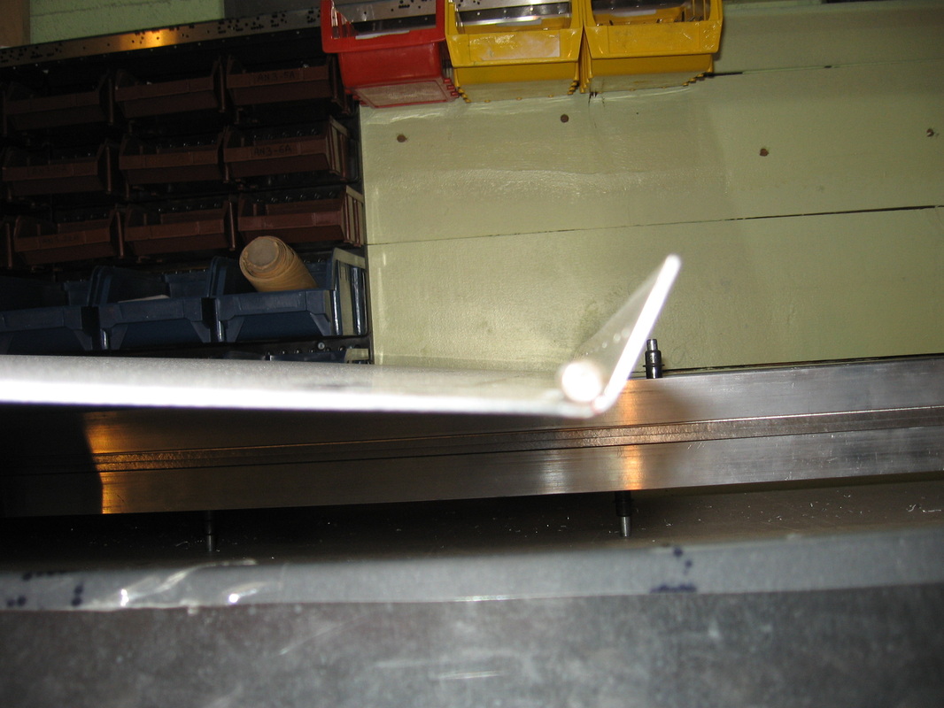
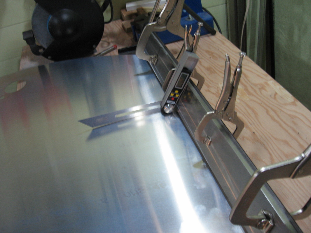
The flap detach angle is 1/4" proud of F12-05 and 06
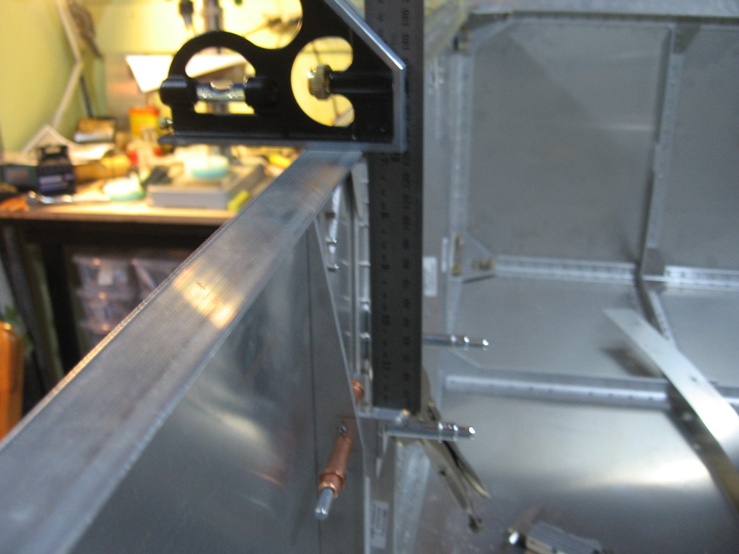
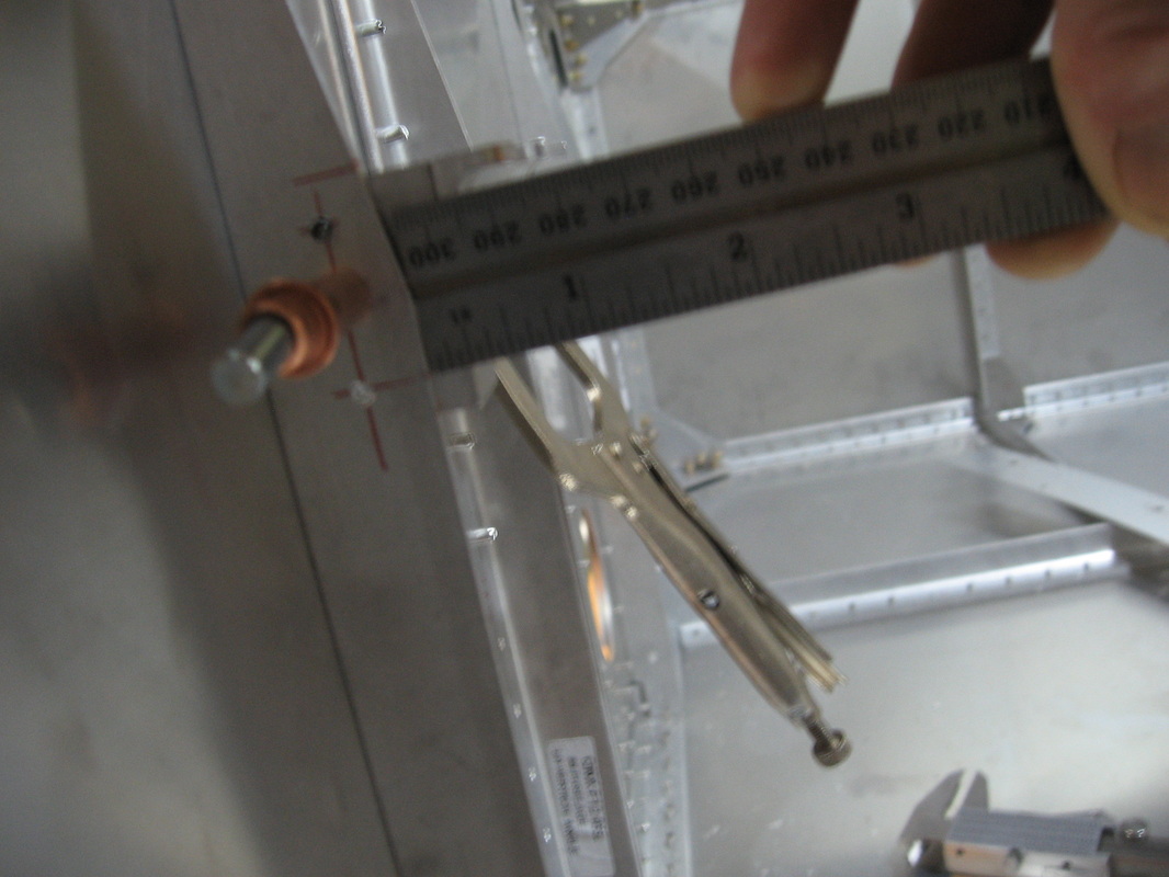
Setting the horizontal distance down from the top longeron
Drilling the 3 holes starting a 1/4 down and then two 1/2 inch spaces.
I used a 3/32" bit to start the holes ,just enough to give my 12" bit something to grab on to.You have to use a 12" bit here or your holes will go in at an angle.
A 90* attachment to your drill will probably work also but i find it hard to keep square to the surface ergo the 12" bit for me.
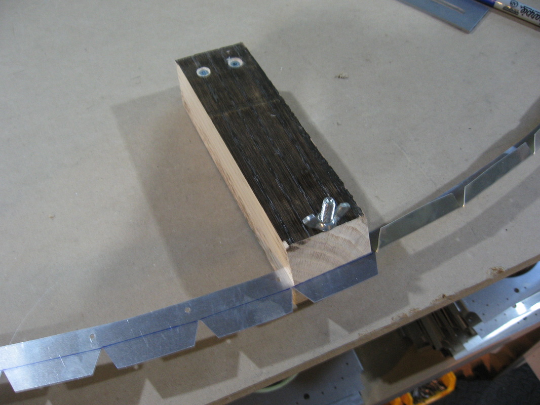
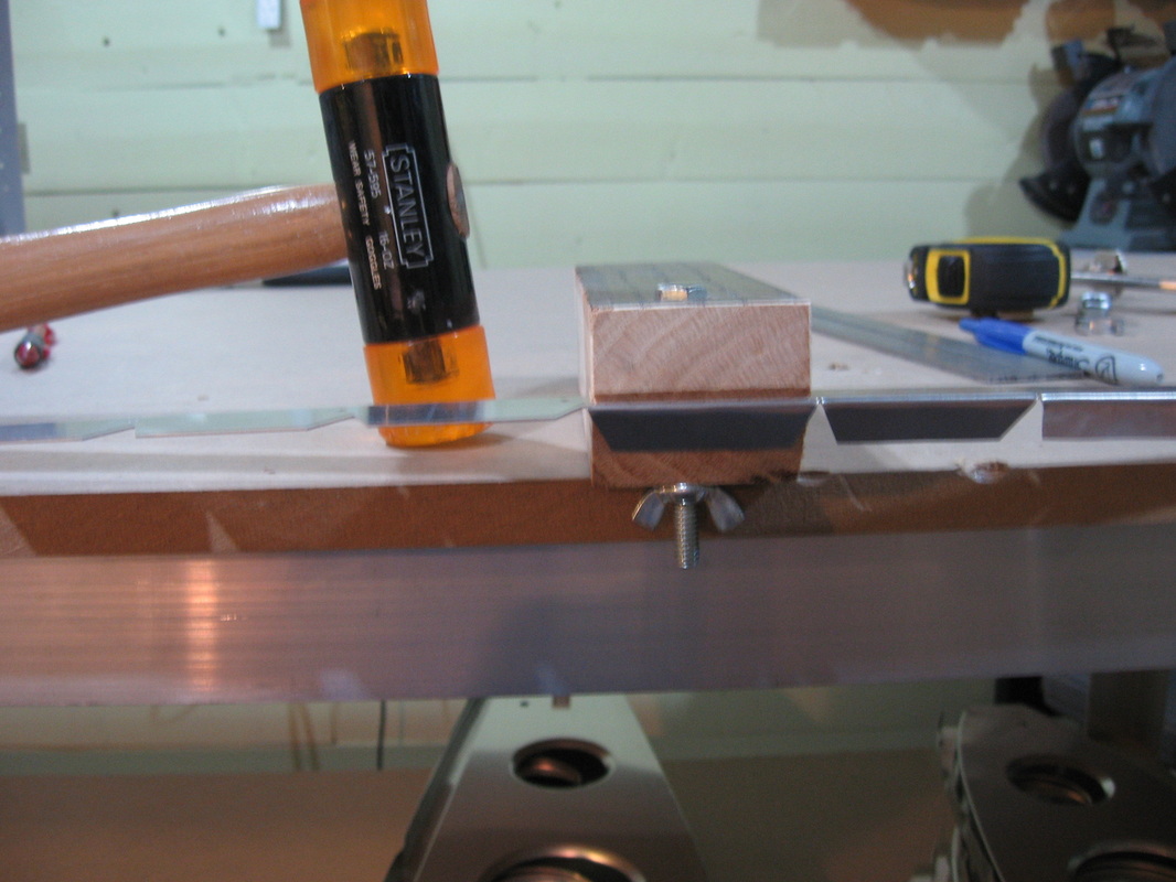
Jig for making the bends on the tabs of the Glareshield Attach Strap on page F04 Two pieces of hardwood screwed together at one end and a wing nut at the other to clamp the strap in .The top piece is cut at 30* .I used a plastic mallet to hammer the bend in.Just flip it over,hang it over the edge of the table holding it steady with one hand while you hammer down with the other.The wing nut will keep it from moving back.
This next bit is dealing with the Firewall former to Glare shield Attach Strap assembly and then fitting the Glare shield on.
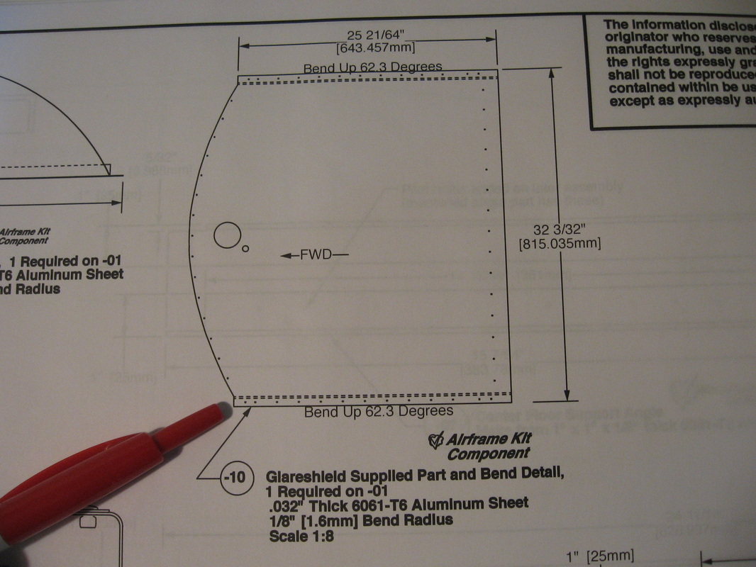
First thing after bending the tabs on the attach strap is putting the 62* bends in the Glare shield.In the pic above it shows 2 dotted lines for the bend.When you put it in your brake you will want to clamp it on the line closest to the edge.Otherwise not the line that intersects the curve.If you use that line you will not be able to line up the holes on the upper firewall former with the center of the glareshield attach strap tabs.You will get the ones at the top drilled to the center but as you move down the holes in the firewall former will start to miss the tab completely.See next pic
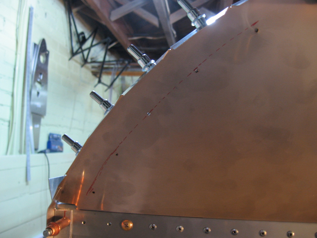
The red line represents the glareshield edge.As you can see it will miss most of the tabs in behind though the ones up near the top have already been drilled to the centers of the tabs.
I took the glareshield and straightened it back up as best I could and then rebent on the line closer to the edge on both sides.In the pic below you can see that I now have all the holes drilled and in the pic after that looking in to the cockpit you can see that all the holes are centered on the tabs.You wouldn't think that moving the bend line over an 1/8" would make such a difference.
In the next pic the higher red line represents where I had bent it the first time which is the line that intersects the curve on the forward end of the glareshield.
The bottom red line is where I clamped it in my brake the second time
Other things to complete while I have the forward fuse on the bench
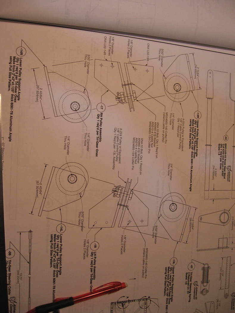
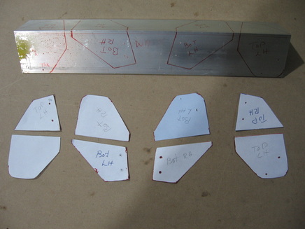
The left and right Pulley Assemblies(page L02) that get attached to the fire wall for the steering.Tail wheel enthusiasts need not apply.
|
|
I made paper templates and traced the pattern onto the angle supplied then cut them on the band saw and cleaned them up with a file and a 3m scotch wheel
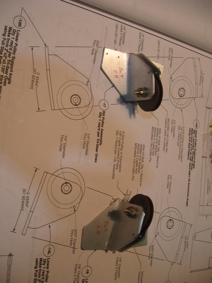
I matched the halves so that they were mirror images of each other,then marked the hole for the pulley and clamped them together then drilled the hole through on the drill press starting with a 1/16" bit and ending with the 1/4" hole called for.Assembled them with the pulley in place and marked where the circumference of the pulley was with a fine sharpie,disassembled them and drilled the hole in one side for the cotter pin then reassembled them and drilled through the other half using the hole just drilled as a guide thereby assuring perfect alignment.
Tricky part is making the templates.You can cut them like you see here but remember to allow for the thickness of the material or just add the appropriate amount to the template and keep them as one piece folding it over the angle and tracing.
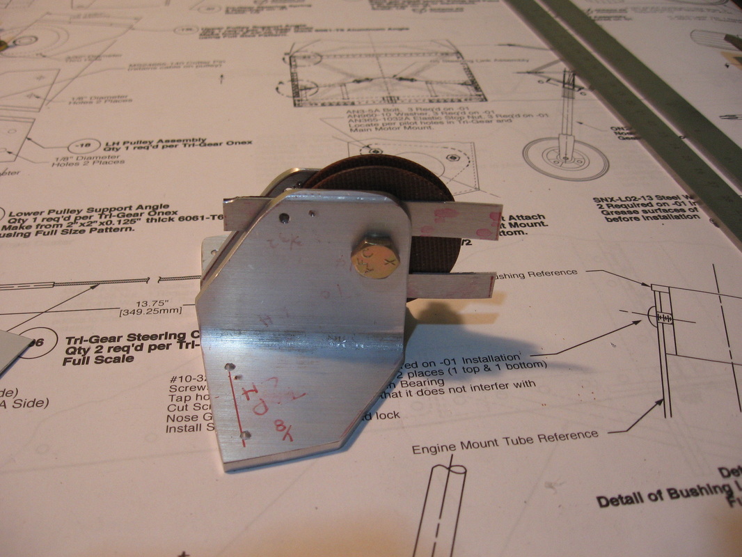
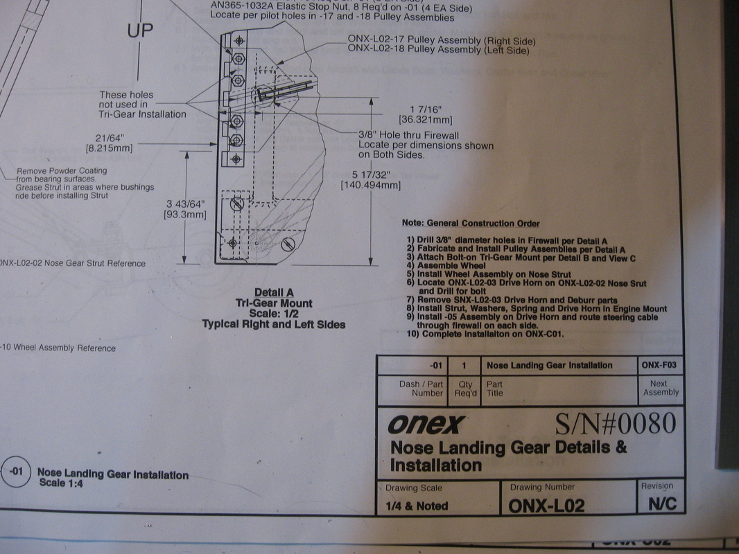
I used shims to give room so the pulley will not bind.I then held it in it's proper place and drilled the holes through the firewall to bolt it in place
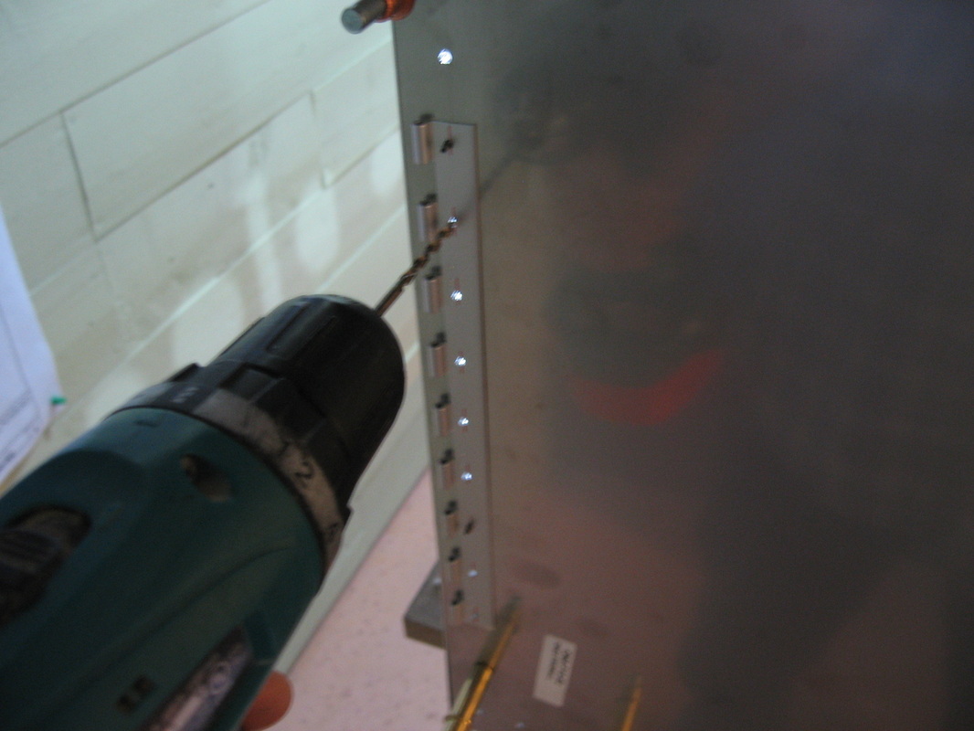
Using the measurements given on L02 detail A, drill the 3/8 hole both sides for the cable to pass through(I used my step drill )then place the assembled pulley in place and start the first hole using the holes you drilled as guides.(The secret to drilling through stainless steel is to use a slow speed and even pressure.If you drill at too fast a speed you will work harden the stainless steel and your drill bit will simply get dull real quick )
|
|
|
|
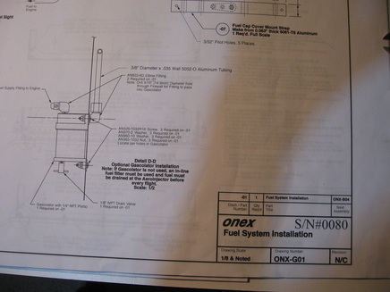
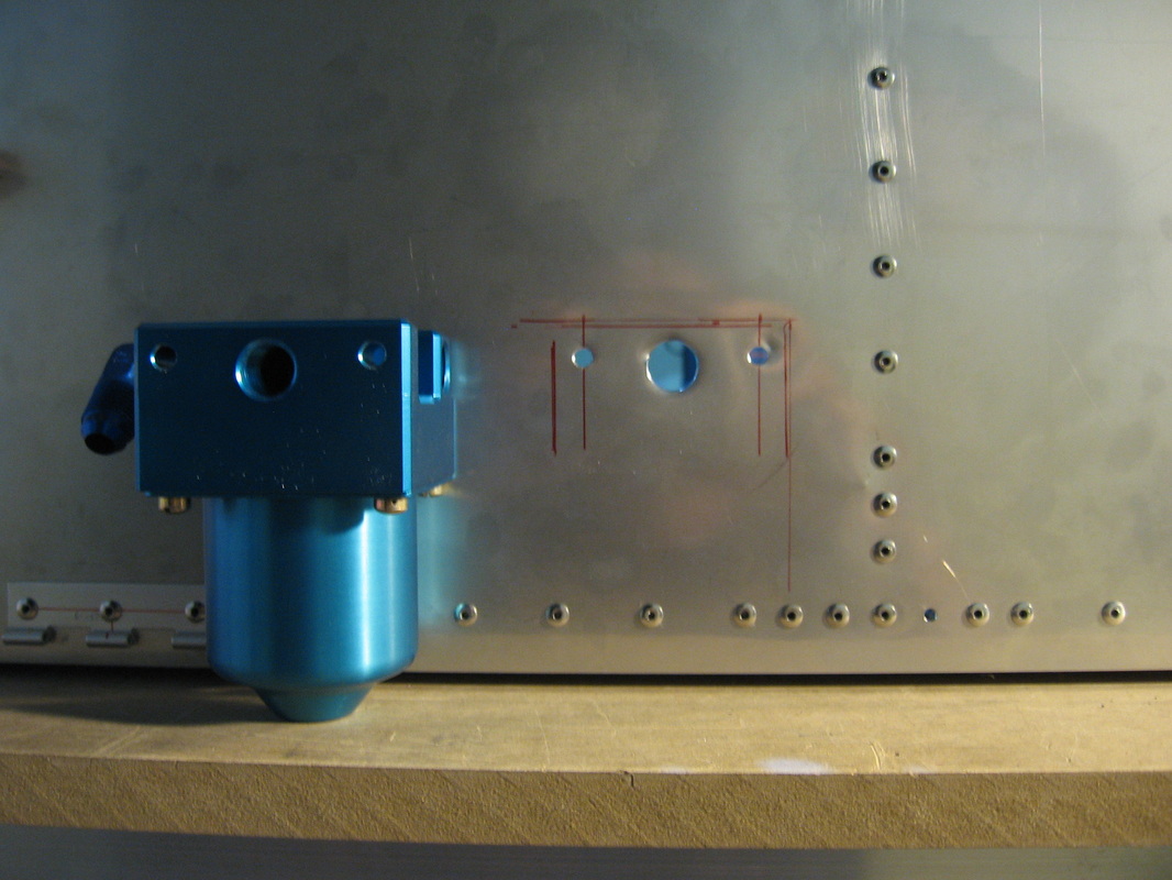
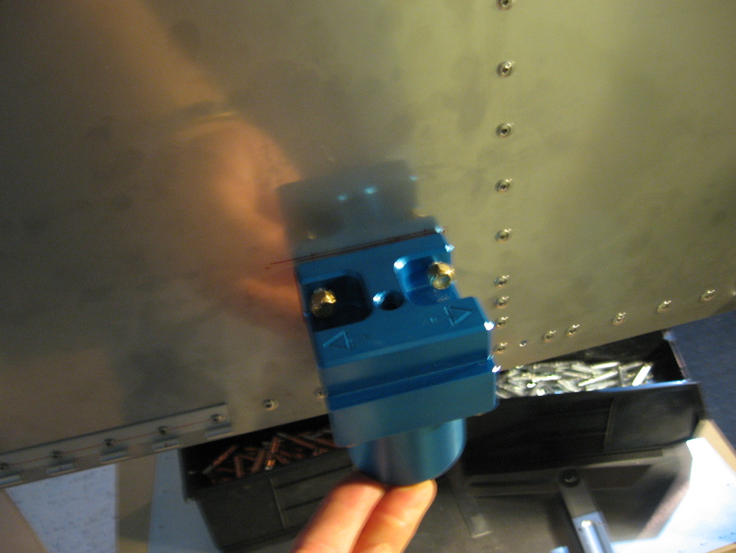
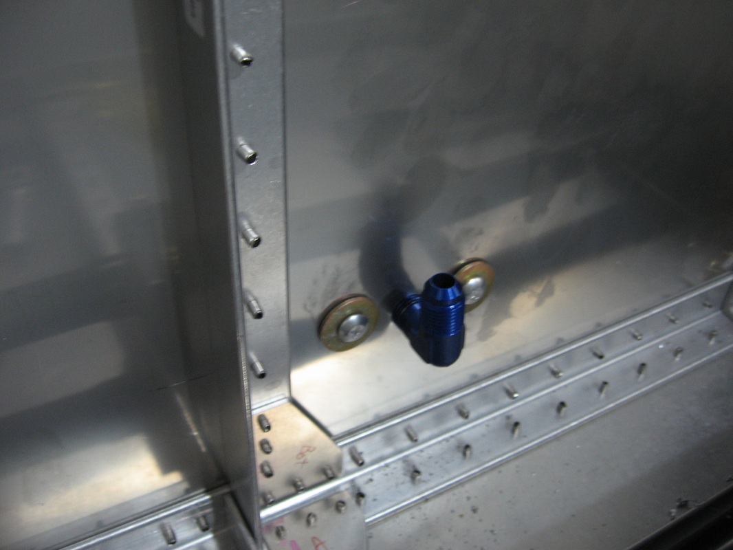
The gascolator can go on now while there is lots of empty space on the firewall.Pretty straight forward .I measured right off the drawing on page ONX G01 they show an outline of it on the left hand side of the page .It's right edge is located 1/8" from center on the drawing which translates to 1" on the actual firewall.Then I traced the outline measured to the center of the fuel line hole on the back side and used my unibit to drill the hole then measured for the bolt holes.Drill slow with even pressure and make sure the bit is sharp.High speed will dull it in short order as the stainless steal hardens.
SEAT INSTALL
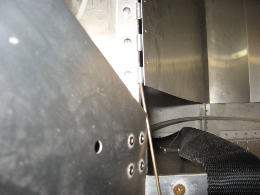
THE PLANS CALL FOR A ONE PIECE PIN FOR THE UPPER SEAT HINGE ATTACH.
THE PIN MATERIAL WOULD HAVE TO BE MADE OF SPRING STEEL TO WORK.AS IT IS THERE IS NO WAY IT WILL FIT BECAUSE OF THE LOCATION,SO I WILL USE A 2 PIECE PIN LIKE THE OTHER PIN LOCATIONS.
THE PIN MATERIAL WOULD HAVE TO BE MADE OF SPRING STEEL TO WORK.AS IT IS THERE IS NO WAY IT WILL FIT BECAUSE OF THE LOCATION,SO I WILL USE A 2 PIECE PIN LIKE THE OTHER PIN LOCATIONS.
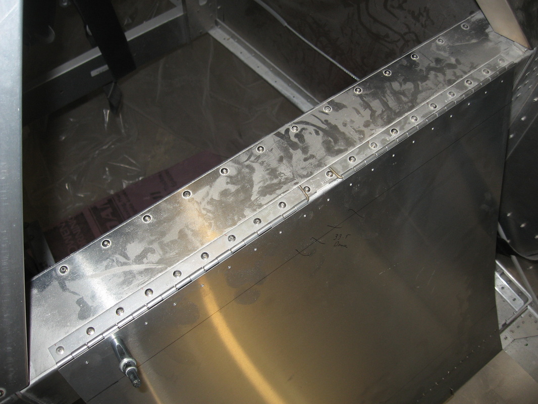
I DRILLED THE HINGE HOLES WITH THE SEAT IN PLACE.THE LOWER HINGE WAS ALREADY IN PLACE AND PINNED